diy solar

diy solar

Is there a purpose for a long ground cable for an RV battery?

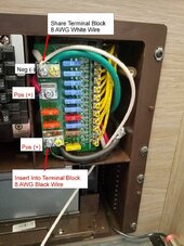
It is possible this is just a common bond (ground) location for all of the different electrical systems they might install into their RVs. I would assume Winnebago understands how to do this after making more than a couple of RVs. Measure the voltage drop if you think there is a problem ... let us know what you find. Theory and practice don't always match up.

I had a bunch of other stuff here, but I'm done now.
 
If I had to guess, and that is all that I can do.
The location of the second conductor connection was due to the preselected location of the first conductor.
In other words, the smaller conductor was already connected to the chassis in this location. And the second conductor was just ran to this existing location.
I wouldn't worry about where it is. Just that it needs to be cleaned up.
 
Would you recommend he move it closer, clean the connection, or add a second?

Also, whatever the grounding is for that smaller green wire under the 1 AWG lug before the frame coating, I would think that ought to move.

I think that the larger cable is moving substantial current where the microwave is on, but it’s not long enough to cause any damage. There has to be a respectable amount of current going in to charge the battery.

Even with RV low standards, I think there’s another cable somewhere, even directly wired, but hard to see.
No microwave or AC. I agree that the battery pulls quite a bit through that connection while charging since there is no b2b converter, but how many amps is that? How did a sheet metal screw pass that kind of current? Anyway, I’ve traced the wiring myself, but here is another schematic that verifies what I’m saying about the battery
IMG_4163.jpeg
 
You don't understand the difference between system negative and ground, you aren't having any problems with it, and you think you can do better by simply shortening that cable? 🤷‍♂️
Winnebago used green from chassis to DC negative in the 12V fuse panel. That could be why you said this (perhaps something else?). I do understand the use of ground in AC circuits and Im not confusing this with a negative feed for a mobile DC system (which turns in to white for the battery converter lol).
 

Attachments

  • 271283883_10166446503875323_8935514321290222535_n.jpg
    271283883_10166446503875323_8935514321290222535_n.jpg
    172.1 KB · Views: 5
Here's what I'm thinking. Determine the location for the new inverter. Determine the wire size and fusing. Wire the inverter positive to battery positive, and inverter negative to battery negative. Enjoy your 120VAC power.

The installation hasn't messed with any of your existing wiring and I will point out that the existing is working just fine as it is. The "why" for where they tied the battery to the frame is anyone's guess. I did see something about the van frame being hybrid (unibody half and body on frame half) so maybe that is it. You can clean the connections up and relocate them in your leisure.

In my trailer I have spent a fair amount of time and effort to understand and improve the wiring choices made at the factory.
 
Back
Top