diy solar

diy solar

Is there a purpose for a long ground cable for an RV battery?

rpgonzalez

New Member
Joined
Jan 27, 2024
Messages
13
Location
Long Beach
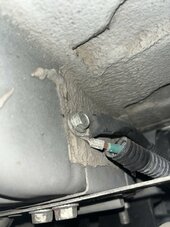
I have a Winnebago Solis camper van (promaster). The ground to chassis is 8 feet long and terminated away from the battery bank. There is all sorts of metal, chassis and frame between the lithium battery bank and the spot where the ground cable is connected to the frame. Nothing else is sharing that ground bolt, the batteries aren’t grounded anywhere else and everything I’ve ever heard is to make that ground cable as short as possible. Yet the designers at Winnebago found a purpose to make it that long (Stretching to the opposite side of the van and then all the way back). Everything else is done as cheap as possible… Why would they waste 8 feet of 1ga copper? Can I move it closer? (the real reason for this question!)
 
Last edited:
I assume you are referring to the battery ground or negative conductor. You are correct in saying the shorter the better. It probably should terminate as close to the largest loads as possible and if it's the engine starting neg cable it should terminate on the starter or close on the engine block. Just saying!
 
Oops. I forgot to mention that the battery bank is for the camper section and not related to the truck functions (lights, starter etc). Although you might be on to something. The 12v fuse panel for lights/fridge/etc is sort of above the location of the ground termination which is under the van (although the ground cable passes that location and keeps going for 3 feet. I want to ground an inverter, perhaps grounding at that location would be good.
 
Couple of questions. Is this chassis cable the only one on the negative side of the bank, or are there some others connected? How does the positive side of the bank get to the 12V fuse panel? Where does the fuse panel pick up the negative?

I suspect that your converter ties positive and negative to the fuse panel. It may have a wire from the fuse panel negative to the chassis, and a positive wire from the panel to the battery bank. That's how my trailer was wired and I never understood why they use the frame as a conductor.

You want to install an inverter as close to the bank as possible because it will need the most current. Running your lights, fans and refrigerator probably pulls less the 15A, an inverter can pull over 100A and needs cables and fuses to handle it.
 
Are you having problems! Or, are you just looking for extra stuff to bring to the scrap yard?
The problem I’m having is that it would seem TO ME that to add an inverter I would want to upgrade my ground wire and MOVE it closer to both the battery and the inverter. Everything on the coach side goes through this ground cable and it SEEMS ludicrous to me that the entire return path goes through such an unnecessarily long cable….

UNLESS there is something that perhaps someone can offer as an explanation. For example, the member who mentioned that the reason the ground cable isn’t right next to the battery is so that it can be closer to the load. Since nobody here has jumped on a different answer and given that the ground bolt to chassis is astoundingly poor then perhaps it’s simple that whoever assembled the van didn’t give a sh*t.
 

Attachments

  • IMG_4151.jpeg
    IMG_4151.jpeg
    144.5 KB · Views: 24
Couple of questions. Is this chassis cable the only one on the negative side of the bank, or are there some others connected? How does the positive side of the bank get to the 12V fuse panel? Where does the fuse panel pick up the negative?
Only one ground cable on the neg post. Pos from battery goes to fuse box. Fuse box is grounded to chassis in 4 different places (not sure exactly why.)
I suspect that your converter ties positive and negative to the fuse panel. It may have a wire from the fuse panel negative to the chassis, and a positive wire from the panel to the battery bank. That's how my trailer was wired and I never understood why they use the frame as a conductor.
Thats all correct. In my controversial opinion, the frame makes the best conductor. It offers less resistance that a 30 ft ground cable, and if you think about sizing ground cables for audio install most manufactures assume the chassis has no voltage drop. But, just my opinion.
You want to install an inverter as close to the bank as possible because it will need the most current. Running your lights, fans and refrigerator probably pulls less the 15A, an inverter can pull over 100A and needs cables and fuses to handle it.
Got it. This is the reason for my post
 
The problem I’m having is that it would seem TO ME that to add an inverter I would want to upgrade my ground wire and MOVE it closer to both the battery and the inverter. Everything on the coach side goes through this ground cable and it SEEMS ludicrous to me that the entire return path goes through such an unnecessarily long cable….

UNLESS there is something that perhaps someone can offer as an explanation. For example, the member who mentioned that the reason the ground cable isn’t right next to the battery is so that it can be closer to the load. Since nobody here has jumped on a different answer and given that the ground bolt to chassis is astoundingly poor then perhaps it’s simple that whoever assembled the van didn’t give a sh*t.
I would connect an inverter directly to the battery. + to + and - to - No need to mess with the existing ground.
 
That picture shows a horrible connection to the chassis. I hope that it's not flowing any current.
Actually, I'm sure that it's not flowing much current. Because it hasn't melted apart.
I would connect an inverter directly to the battery. + to + and - to - No need to mess with the existing ground.
This is the answer.
 
That picture shows a horrible connection to the chassis. I hope that it's not flowing any current.
Actually, I'm sure that it's not flowing much current. Because it hasn't melted apart.

This is the answer.
Would you recommend he move it closer, clean the connection, or add a second?

Also, whatever the grounding is for that smaller green wire under the 1 AWG lug before the frame coating, I would think that ought to move.

I think that the larger cable is moving substantial current where the microwave is on, but it’s not long enough to cause any damage. There has to be a respectable amount of current going in to charge the battery.

Even with RV low standards, I think there’s another cable somewhere, even directly wired, but hard to see.
That connection isn't doing much.
If it were, it would be discolored at the minimum.

Clean up the connection surfaces.
Leave it where it is.
And forget that it's there.
 
The problem I’m having is that it would seem TO ME that to add an inverter I would want to upgrade my ground wire and MOVE it closer to both the battery and the inverter. Everything on the coach side goes through this ground cable and it SEEMS ludicrous to me that the entire return path goes through such an unnecessarily long cable….

UNLESS there is something that perhaps someone can offer as an explanation. For example, the member who mentioned that the reason the ground cable isn’t right next to the battery is so that it can be closer to the load. Since nobody here has jumped on a different answer and given that the ground bolt to chassis is astoundingly poor then perhaps it’s simple that whoever assembled the van didn’t give a sh*t.
Typical for the rv industry. On ours they left out a wire so the a/c didn't work. It was a known problem and still.......you know the rest type of contest.
 
That picture shows a horrible connection to the chassis. I hope that it's not flowing any current.
Actually, I'm sure that it's not flowing much current. Because it hasn't melted apart.

This is the answer.
It’s definitely running the entire van. That being said it doesn’t have AC, microwave… On the other hand, that is the connection point for charging the battery straight from the alternator, so I’m sure that connection sees up to 60 or even 100amps. Yes it is horrible… that’s my original post.
 
So what you are saying is this is the system negative, not just the ground?

I would still leave it as is and connect an inverter directly to the battery.
 
That connection isn't doing much.
If it were, it would be discolored at the minimum.

Clean up the connection surfaces.
Leave it where it is.
And forget that it's there.
It handles about 5-15A max from the coach functions, but it’s also ground for charging the batteries from the alternator. Definitely sees a lot of action.
 
So what you are saying is this is the system negative, not just the ground?

I would still leave it as is and connect an inverter directly to the battery.
The green cable goes to the 12V fuse box and the black cable goes to the battery. It’s the only battery connection (except the solar controller, so maybe the controller is grounded too?).

After advice here, I’m definitely not leaving it alone lol
 
It handles about 5-15A max from the coach functions, but it’s also ground for charging the batteries from the alternator. Definitely sees a lot of action.
I think that you are confusing ground and negative.
The green cable goes to the 12V fuse box and the black cable goes to the battery. It’s the only battery connection (except the solar controller, so maybe the controller is grounded too?).
It sounds like any current flowing through that connection would be from lug to lug. (Not through lug to chassis) which is negative to negative.

Just clean it up and make it right.
But don't use it for anything else.
Connect the inverter directly to the battery/ or battery system bus bars.
It's best to keep large loads on conductors and not through the chassis.
 
The green cable goes to the 12V fuse box and the black cable goes to the battery. It’s the only battery connection (except the solar controller, so maybe the controller is grounded too?).

After advice here, I’m definitely not leaving it alone lol
You don't understand the difference between system negative and ground, you aren't having any problems with it, and you think you can do better by simply shortening that cable? 🤷‍♂️
 
I think that you are confusing ground and negative.
So what’s it called when the negative terminal of a battery is connected to the chassis and everything else is powered off the chassis?

It sounds like any current flowing through that connection would be from lug to lug. (Not through lug to chassis) which is negative to negative.

I guess I am confused

Just clean it up and make it right.
But don't use it for anything else.
Connect the inverter directly to the battery/ or battery system bus bars.
It's best to keep large loads on conductors and not through the chassis.

the inverter conversation is getting in to the weeds. There is no inverter yet, as my initial question revolves around managing the way the battery is connected to the chassis. As you can see, that connection point sucks AND the question is all about the length of the cable. I have people telling me to leave it alone and others questioning my ability to follow a cable. That’s all great and all, but I just want to know if there is a reason this cable is so long? Unless someone has something to offer like “you need resistance for blah blah blah” then I should change it. Especially when you tell me large loads need to be attached to the battery… and this is the ONLY connection point to the alternator (through the chassis all the way to the front 20 ft away where the alternator is attached to the chassis). If I clean it up and leave it that way, the alternator will still charge the house batteries (full current, no DCDC b2b converter) through the chassis, to the screw, into that cable and then to the battery.
 
You don't understand the difference between system negative and ground, you aren't having any problems with it, and you think you can do better by simply shortening that cable? 🤷‍♂️
lol. It’s not a lack of comprehension, it’s a lack of using terminology that makes sense to you. Since you haven’t enlightened me I will continue to used the wrong vocab. Thanks.

AM I having problems with it? According to everyone on this thread, I WILL have problems. Should I wait it for it to cause a fire?

Yes, shortening a cable will reduce its voltage drop. If I plan to add a 60a DC-DC for example, changing a 1awg cable from 9 ft to 4 ft increases its capacity. I can’t verify how much current the house pulls when the truma, water pump and fridge are all active but I know it’s all going through that “ground”.
 
Back
Top