This leaves me wondering why the inverter operated flawlessly for the past year without ever pre-charging it and this is with me routinely turning the master power switch on/off between trips. The no power problem occurred after the inverter provided power to successfully run the coffee maker cycle and had been connected to the batteries for several days. I'm not doubting your theory and will attempt to pre-charge the inverter, I remember reading this could be done with a 12v light bulb.Most likely the problem is not your specific inverter.
What you are describing is what happens when there is a surge of power draw to charge up the capacitors on the input stage of inverters. Basically the current surge trips the battery bms.
Just do a search on pre-charging inverters for solutions.


You are using an out of date browser. It may not display this or other websites correctly.
You should upgrade or use an alternative browser.
You should upgrade or use an alternative browser.
Batteries died and will not accept charge. Help!
- Thread starter WNCGUY
- Start date
HarryN
Solar Enthusiast
This leaves me wondering why the inverter operated flawlessly for the past year without ever pre-charging it and this is with me routinely turning the master power switch on/off between trips. The no power problem occurred after the inverter provided power to successfully run the coffee maker cycle and had been connected to the batteries for several days. I'm not doubting your theory and will attempt to pre-charge the inverter, I remember reading this could be done with a 12v light bulb.
As far as the inverter, it is possible that it has a hard fault of some kind - they do fail that is for sure.
If you have the ability to open it up and look / diagnose it can be fun, but most people cannot really repair them.
It is too bad that you are not closer, or we could just put on an 1100 watt / 12 volt inverters that I have sitting here.
The only good way to test what is really happening is with a clamp meter. This could tell you what is going on in each wire of your system. I own a couple - one for getting into tight spots and measuring smaller wires, and another for larger wires.
There are many brands out there, I use these from extech:
Model: 380950 and 380947 or much cheaper MA445
Sorry - would give you links to them but I don't think that it is allowed.
__________
As far as "why" electronics get wacky sometimes, I don't know. One of my most personally annoying memories is that I built an electrical system for a customer, and as usual, put it on the test stand for a week to make sure it was good. Ran perfectly - sent to customer and one of the rock solid chargers that I use failed 3 days later while he was on a trip. This was not a cheapo charger, it was a high end one.
Pulled a spare off the shelf, had a buddy of mine test it (he is an aerospace electrical engineer) - same exact thing happened again.
Ended up having to do a design change that literally no one, including the suppliers - would be required. Worked for multiple years now - but what a pain. Things just don't always show up right away.
Last edited:
HarryN
Solar Enthusiast
I made a little test fixture for fun to demonstrate a simple method of pre-charging an inverter with just a solar panel.
It is just some parts that I had sitting on the shelf. Very simple but it works.

 diysolarforum.com
It is just some parts that I had sitting on the shelf. Very simple but it works.
Small test fixture
Sometimes it is easier to show people things in photos than to describe them. So I made a little test fixture from left over parts, nothing fancy. In this case, some people asked about methods of dealing with pre-charging the capacitors on the input stage of inverters, and I had suggested that...
diysolarforum.com
Originally the problem manifested while the inverter was in use, so it doesn't seem likely to me that the root of the problem is the inverter needing to be pre-charged. Also, it's only a 1500w inverter, isn't this typically only an issue with higher capacity inverters?
Wouldn't a short circuit in the inverter cause the BMS to behave in the same way?
Wouldn't a short circuit in the inverter cause the BMS to behave in the same way?
HarryN
Solar Enthusiast
Originally the problem manifested while the inverter was in use, so it doesn't seem likely to me that the root of the problem is the inverter needing to be pre-charged. Also, it's only a 1500w inverter, isn't this typically only an issue with higher capacity inverters?
Wouldn't a short circuit in the inverter cause the BMS to behave in the same way?
The problems related to the pre-charge will happen to any inverter with decent input caps, even 1 kW versions.
It would be nice if we saw a photo or diagram of exactly how it was wired and the components.
What I "suspect" is that at some point at least 1 battery bms tripped and has not re-set, so the system is really running on only 1 battery, so it appears to work with the 12 volt portion of the system.
Adding the inverter causes that one to trip. That is speculation on my part, but I have seen it happen before.
You are right that if there is an internal short in the inverter - it would do the same behavior. It is just that a decent 1500 watt inverter is $ 1K, so I was just trying to see if anything else might be the problem. Maybe that is the easiest approach to try.
If the batteries are all wired in parallel, with no means to isolate them individually with a switch or breaker setup, then it is challenging to know if it is a bms problem or an inverter problem.
Attempted to pre-charge the inverter today using the resister shown in the below pic. While holding the positive cable that is connected to the inverter, I held the resister to the cables other end and touched the resister to the battery connection point (Victron lynx distributor hacked with fuses). There was an almost unnoticeable spark but within I will say 6-7 seconds the resister got too hot to continue holding so I removed resister and immediately touched the inverter positive cable to the battery connection where I got a larger spark that made me pull the cable away. I am of the opinion pre-charging was unsuccessful since there should have been no spark.
Next steps and or suggestions.

@HarryN mentioned a system pic. The system is in a Toyota Sienna minivan, setting in the storage area for third row seats. The inverter connects to the Victron lynx distributor 200-amp fuse. Any questions on please ask me.

Next steps and or suggestions.
@HarryN mentioned a system pic. The system is in a Toyota Sienna minivan, setting in the storage area for third row seats. The inverter connects to the Victron lynx distributor 200-amp fuse. Any questions on please ask me.
Last edited:
HarryN
Solar Enthusiast
Thanks - that helps. For fun, try measuring the resistance on the inverter or the connections to it from (+) to (-).
The DC path to the inverter.
It should measure very high resistance - like mega ohm levels if the inverter is good.
Make sure that the power is turned off, the system is essentially at zero volts, and there isn't any other path for electricity to go other than through the inverter (+) and (-)
Meters can be funny sometimes, so double check that touching the leads to each other gives essentially a zero resistance number.
______________
sunshine_eggo
Happy Breffast!
Was the inverter off? It must be off when you do the precharge.
Thanks - that helps. For fun, try measuring the resistance on the inverter or the connections to it from (+) to (-).
The DC path to the inverter.
It should measure very high resistance - like mega ohm levels if the inverter is good.
Make sure that the power is turned off, the system is essentially at zero volts, and there isn't any other path for electricity to go other than through the inverter (+) and (-)
Meters can be funny sometimes, so double check that touching the leads to each other gives essentially a zero resistance number.
______________
With inverter completely disconnected and measuring no voltage, the resistance at the +/- connections started low and ramped up leveling at 4.23. The GoWise 1500 has a built-in push power button and remote, so I first tested without pressing the power button and then retested after pressing the button. No change in measurement result.
Was the inverter off? It must be off when you do the precharge.
I think the power button default is off, but to be sure I tried pre-charging with and without pressing the button. Same results with both attempts, with resister held to the inverter and touching + at fuse got a larger spark and resister got hot.
After checking that I still had power from the battery I turned the system power switch off, connected the inverter, turned power switch on and noticed the inverter green power light came on for a second and then faded away. Found did not have 12v battery power so disconnected inverter, applied IP22 charger for less than a minute and restored battery power.
HarryN
Solar Enthusiast
With inverter completely disconnected and measuring no voltage, the resistance at the +/- connections started low and ramped up leveling at 4.23. The GoWise 1500 has a built-in push power button and remote, so I first tested without pressing the power button and then retested after pressing the button. No change in measurement result.
Thanks for doing this test - sorry for not thinking about it before.
The resistance should be very high - like mega ohms - at least that is why the inverter on my test bench measures.
It looks like it is time to replace it.
Maybe take the old one apart for fun as a learning experience if you like.
With the cost of a higher end inverter being $600+, I think I'm going to roll the dice and buy another GOWISE, or maybe try a GIANDEL and hope it will last a few years unless anyone has a lead of a good sale going on.
Thinking of what may have contributed to the inverter failure. 1500w inverter that I use for about 15min to power a 900w coffee maker a once coffee is brewed shut off and then use a 1800w conduction cooktop that when first turned-on defaults to setting 5, 820w and I have not used it past setting 6.5, 1100 watts and only for about 10 minutes at a time.
Wondering what effect, the lack of pre-charging the inverter had on this failure. In the last six mounts I've probably turned the main power switch on/off a dozen times between trips and when checking connections, fiddling with the system.
I Need to start pre-charging, referring to my system picture in post 26, would I be able to pre-charge with the inverter connected to the system, main power switch in off, and simply jumping a resister or 12v bulb from the class T fuse to the inverter + connection point and then turning mail power on?
Also noticed when connecting my IP22 charger to batteries I get a spark, I connect the charger via Anderson connecter then plug the charger into the wall outlet. Do I need to pre-charge the IP22 charger?
EDIT: Could I make the pre-charge jumper with a 12v, 26.9w DC automotive bulb #1156 and socket?
Last edited:
HarryN
Solar Enthusiast
With the cost of a higher end inverter being $600+, I think I'm going to roll the dice and buy another GOWISE, or maybe try a GIANDEL and hope it will last a few years unless anyone has a lead of a good sale going on.
Thinking of what may have contributed to the inverter failure. 1500w inverter that I use for about 15min to power a 900w coffee maker a once coffee is brewed shut off and then use a 1800w conduction cooktop that when first turned-on defaults to setting 5, 820w and I have not used it past setting 6.5, 1100 watts and only for about 10 minutes at a time.
Wondering what effect, the lack of pre-charging the inverter had on this failure. In the last six mounts I've probably turned the main power switch on/off a dozen times between trips and when checking connections, fiddling with the system.
I Need to start pre-charging, referring to my system picture in post 26, would I be able to pre-charge with the inverter connected to the system, main power switch in off, and simply jumping a resister or 12v bulb from the class T fuse to the inverter + connection point and then turning mail power on?
Also noticed when connecting my IP22 charger to batteries I get a spark, I connect the charger via Anderson connecter then plug the charger into the wall outlet. Do I need to pre-charge the IP22 charger?
EDIT: Could I make the pre-charge jumper with a 12v, 26.9w DC automotive bulb #1156 and socket?
Thank you for posting your use case and the appliances - this tells us a lot.
The coffee maker is a resistive load, and that is the easiest load to power for an inverter. While they might cycle the heater a little bit, the couple of them that I have tested never really pulled more than the rated power listed. Really any even mediocre inverter can power a resistive load like this.
The induction cooker, similar to a motor, is an inductive load, and this is much more difficult for an inverter to run, and some inverters cannot run them at all. This is what separates an entry level inverter from a higher end inverter.
The second aspect about cook tops in general is less obvious. While a small number of them do in fact turn down the power level when you turn down the dial, the majority do not. What many of them do instead is cycle "full power" on / off with a timer to average out to the desired total power level on the dial. In other words, it is possible that it is really pulling pulses of 1800 watts.
So it depends very much on your exact inductive cook top if it cycles to make an average, vs really turns it down. I don't remember which ones work one way or another, when I deal with this - I just use a really good quality 2 000 watt inverter, but the one that I use is 3x your plan.
__________
I still think that the easiest way to pre-charge your circuit is to just add a very small solar panel, directly connected to the bus bar with a breaker or fuse, just like I showed in the link. It can be very small and even inside getting just ambient light. In a few minutes it will gently pre-charge your setup - just turn it off when it is all charged up. (post #23 of this thread ) 5 - 10 watts is plenty.
In general, I don't see a point in turning off a van power system at all. Just have it running 24/ 7 and turn off the inverter when not in use. That will keep it pre-charged all of the time. If it isn't capable of running parked at home, it isn't going to be capable of running during a vacation.
As far as the 120 vac charger - most of them just do that - would not worry about it. All of my IOTAs do it, the only charger that I own that does not is my dual pro, but that is a very specialized charger.
Last edited:
Decided to take some current measurements from the Duxtop Model BT-200DZ induction cook top to find out if it pulsated 100% power on and off or actually provided variable power settings. Below are the factory power settings and my results using a clamp meter.
Although I didn't test all 20 settings, starting at 3.0, a lower setting then I would use, indeed the power cycles on and off continuously, I assume lower settings would do the same.
For settings 4.0 up, I tested selected settings for about 2 minutes each while bringing a pot of water to boiling the current did slightly drift but I didn't see any indication of cycling on/off/on. Results indicate the cooktop is not capable of the published 1800w, highest recorded at setpoint 10 is 1452w. Unless I am missing something I don't think using cooktop killed the inverter, and 1500w shouldn't have an issue, perhaps running no higher than power setting 8.0, 1247/1255w (Highest setting ever used was 6.5, 1874/1080w).
Pre-charging.
I need a way to pre-charge not only when home but also if problems arise when traveling so a solar panel, even a very small one is a nogo to carry in a minivan, this is why I am thinking 12v bulb/socket and the method of pre-charging I described in previous post, fits right in my tool kit but need to know if it will work as I described? I've seen posts on this site where some use a #2 pencil but like being able to see the light bulb glow.
HarryN
Solar Enthusiast
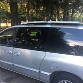
This is a 2000 dodge mini van that I used to own. It sacrificed itself to keep me alive when a pickup ran a light going pretty fast.
Anyway, there are two solar panels up on top mounted to the factory roof top rails as an example of what can be done.
For a 12 or 24 volt system, you can easily put a bogart solar controller on and it will pre-charge your inverter if you want to do it.
I get it if you are trying to avoid this path.
Right now I am driving a 95 explorer with one panel facing front to back - one that my son and a friend removed from the van when I was not able to do it.
The panels are obvious in the photo, but in the real world, since they are right at eye level, and a lot of people locally use ski racks to go to Tahoe - no one noticed.
Attachments
HarryN
Solar Enthusiast
Decided to take some current measurements from the Duxtop Model BT-200DZ induction cook top to find out if it pulsated 100% power on and off or actually provided variable power settings. Below are the factory power settings and my results using a clamp meter.
Although I didn't test all 20 settings, starting at 3.0, a lower setting then I would use, indeed the power cycles on and off continuously, I assume lower settings would do the same.
For settings 4.0 up, I tested selected settings for about 2 minutes each while bringing a pot of water to boiling the current did slightly drift but I didn't see any indication of cycling on/off/on. Results indicate the cooktop is not capable of the published 1800w, highest recorded at setpoint 10 is 1452w. Unless I am missing something I don't think using cooktop killed the inverter, and 1500w shouldn't have an issue, perhaps running no higher than power setting 8.0, 1247/1255w (Highest setting ever used was 6.5, 1874/1080w).
Pre-charging.
I need a way to pre-charge not only when home but also if problems arise when traveling so a solar panel, even a very small one is a nogo to carry in a minivan, this is why I am thinking 12v bulb/socket and the method of pre-charging I described in previous post, fits right in my tool kit but need to know if it will work as I described? I've seen posts on this site where some use a #2 pencil but like being able to see the light bulb glow.
View attachment 193932 View attachment 193955
I don't know if it will work or not, but it is easy enough to try when you get the new inverter.
Similar threads
- Replies
- 41
- Views
- 1K