JJenkins5179
New Member
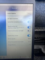
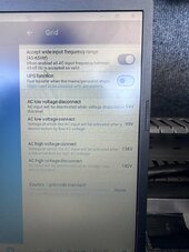
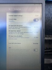
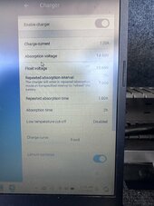
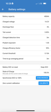
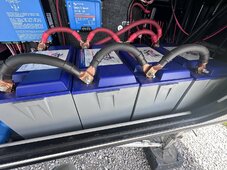
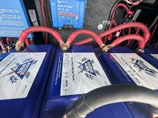
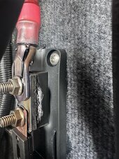
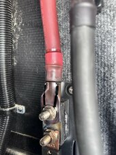
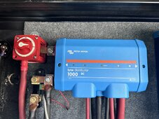
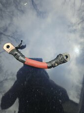
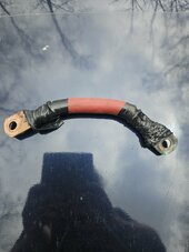
Hey everyone. Looking for some assistance/guidance. I have a setup that was intended to allow my wife to brew a cup of coffee when we were dry camping/boondocking. I have 4 Battle Born 100 Ah, 12V batteries, a Victron 12/3000/120-50 2 x 120v Charger/inverter. Batteries are wired in parallel with 4/0 wire, positive wire has a 400A ANL fuse in line before it goes to a battery disconnect switch. From there is goes to a BMV-712 Smart shunt, Lynx distributor. The problem is anytime I try and run anything that consumes any significant power the system dies within seconds. I have checked all connections and they are tight and in the correct spot. All settings have been checked and appear to be right. From what I have seen it seems that I should be able to power a Keurig single cup coffee maker with the battery setup I have. And to make matters worse when I went out to verify everything was tight and secure I noticed that the wire from the ANL fuse holder to the disconnect switch had gotten very hot at some point but the fuse was not blown. I have checked all batteries independently and all are good and fully charged. I have included pics of what my settings are. Any help would be greatly appreciated! Thanks!
Josh
Josh