JPiskun87
New Member
This is a great thread for those using a lifepro4 with a rover 20/30/40. If others find themselves here I’ve come to learn there are 2 different Bluetooth apps for the rovers. The original was the BT app which had more parameter adjustments in the “user” setting. Renogy no longer updates that app and the BT modules are now meant to be used with the “DC Home” app. When adjusting parameters in the “user” settings your options are a little different.
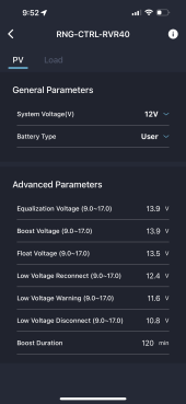
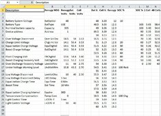
Equalization Voltage
Boost Voltage
Float Voltage
Low Voltage Reconnect
Low voltage warning
Low voltage disconnect
Boost Duration
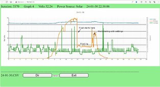
I have a brand new lifepo4 that came at 13.3v. I’ve been charging it when I can after work and finally reached up to 14.2v on the battery monitor. Even though my equalization and boost settings were set to the manufacturers specs of 14.4 I started to receive an E02 error which is “Battery Over Voltage” it wasn’t until I moved them down to 13.9 the controller would successfully move from “bulk” to “boost” and then into “float” without setting off any errors.
Equalization Voltage
Boost Voltage
Float Voltage
Low Voltage Reconnect
Low voltage warning
Low voltage disconnect
Boost Duration
I have a brand new lifepo4 that came at 13.3v. I’ve been charging it when I can after work and finally reached up to 14.2v on the battery monitor. Even though my equalization and boost settings were set to the manufacturers specs of 14.4 I started to receive an E02 error which is “Battery Over Voltage” it wasn’t until I moved them down to 13.9 the controller would successfully move from “bulk” to “boost” and then into “float” without setting off any errors.