diy solar

diy solar

Renogy 40a mppt Li settings

Thanks for the info, I get no heat from the 2 awg wire so that's good for me. Just ordered a 40a circuit breaker to go between the charge controller and batteries plus the Blue Sea 5191 terminal block and 200a fuse today.

The 8 guage is less than 2 feet and I did find a little heat when the controller puts out close to max amps so I ordered a set of 6 guage to try out on the controller.

Glad to hear the fuse & breaker are ordered. Suggest they be Installed ASAP.

The 2 gauge wire at the lower loads that are running on the system should not get warm. If or when large loads are placed on the inverter for a time the 2 gauge wire will heat up. Nothing wrong with the wire getting warm as long as not hot when higher currents are flowing. The heat felt in the wire are losses though. A bigger size wire would be better, but the way the system is currently used 2 gauge is good. If system demand increases significantly and the wire gets hot 1/0 gauge wire would be a good choice.

The 8 gauge wire was getting warm at near 40 amps from the Rover 40, but that was OK. 8 gauge wire at 2 feet long with 40 amps is only 0.5% loss in heat. Nothing wrong with the 6 gauge and it will have less losses. Bigger wire is usually better. If my recollection serves me right, the Rover 40 will only accept 8 gauge as the largest wire. Might have to cut a few strands of wire off on the stripped ends to get the 6 gauge wire in the Rover 40 clamp terminals, but that is OK and really little to no loss. Check that no stray strands of wire are out of the Rover 40 terminal clamps with the 6 gauge wire.

If you find the 6 gauge wire is more pain than it is worth the 8 gauge wire is good for the Rover 40.
 
Last edited:
Good to know but I don't plan on spending another 1000 bucks right now and shore power is planned for my cabin area in 2023. Good to know for the future, thanks.
That was just for anyone who read the statement above mine about recommendations for strings of the 100 amp batteries.

(“Somehow I believe they'll stay the same since CHINS recommends only combining 4 batteries in parallel.”)

keep us posted on progress please.
 
That was just for anyone who read the statement above mine about recommendations for strings of the 100 amp batteries.

(“Somehow I believe they'll stay the same since CHINS recommends only combining 4 batteries in parallel.”)

keep us posted on progress please.

Glad to hear the fuse & breaker are ordered. Suggest they be Installed ASAP.

The 2 gauge wire at the lower loads that are running on the system should not get warm. If or when large loads are placed on the inverter for a time the 2 gauge wire will heat up. Nothing wrong with the wire getting warm as long as not hot when higher currents are flowing. The heat felt in the wire are losses though. A bigger size wire would be better, but the way the system is currently used 2 gauge is good. If system demand increases significantly and the wire gets hot 1/0 gauge wire would be a good choice.

The 8 gauge wire was getting warm at near 40 amps from the Rover 40, but that was OK. 8 gauge wire at 2 feet long with 40 amps is only 0.5% loss in heat. Nothing wrong with the 6 gauge and it will have less losses. Bigger wire is usually better. If my recollection serves me right, the Rover 40 will only accept 8 gauge as the largest wire. Might have to cut a few strands of wire off on the stripped ends to get the 6 gauge wire in the Rover 40 clamp terminals, but that is OK and really little to no loss. Check that no stray strands of wire are out of the Rover 40 terminal clamps with the 6 gauge wire.

If you find the 6 gauge wire is more pain than it is worth the 8 gauge wire is good for the Rover 40.
Absolutely if I were using larger current draws on my system i would need to upgrade that 2 guage wire. For this reason I don't use the toaster, keurig or larger power tools on it. That's when the generator comes out. I've not seen any stress on the system when I use low power items like the tv, dvd player, sound bar (Total around 175 watts) and lights generally run around 7-10 watts each. Power goes up by about 100 watts when the water pump cuts in but that only runs for about 3 minutes at a time to fill my pressure tank. I've had my hands on those wires on the batteries etc many times and they are always cold. I actually I know I'm using it well because the inverter fans never cut in. They have when I tested the Keurig on it.

I will have to check the 8 guage wires coming out of the controller, and I may have to reattach that positive going to the batteries. Renogy should address the lug issues, I've seen many people address this in their videos. I'm getting 2 x 4 foot 6 guages wires which I will cut down for the controller and yes I did think I may have to remove a few strands.

Have you seen any glaring issues with my user settings on the app?
 
Have you seen any glaring issues with my user settings on the app?

Looks like the Float Charge Volt and Boost Char Return Volt is a little to close as my preference is at least 0.2 volts. Recommend setting Float to 13.5. Low Voltage Alarm is set kind of high at 12.7 and may give you nuisance alarms and recommend setting to 12 volts. Recommend dropping Over Disc Return to 12.1 volts.

Over time you will find the best settings for your system.

Below are my settings, but note that the system never sees low voltages because the Samlex EVO inverter/charger built in transfer switch transfers load power to the grid when battery is at 12.5 volts (actually 25 volt because 24 volt system) and charges the battery. So I purposely have my low voltage setting set below the transfer setting and am not concerned with those settings. Below are my best known descriptions that may help setting your own.

Renogy Rover Solar Charge Controller with Rover BT App and SRNE App Settings Explained
Note: Rovers often read 0.1 to 0.2 Volts low. So at 14.2 volts actual volts Rover reads 14.0 to 14.1.

Note: Renogy Rover Solar Charge Controllers only have settings for 12 volt systems. For 24 volt systems double values and for 48 volt systems multiply by 4. So a 14 volt boost would be 28 in 24 volt system and 56 in a 48 volt system. Need Rover 60 or 100 amp for 48 volt systems.

Note: On a 12 volt system the settings resolution is 0.1 volts. On a 24 volt volt system the settings resolution is 0.2 volts and on a 48 volt system the settings resolution is 0.4 volts.

Note: These are the best known explanations at time of writing. Some of the listed explanations may be in error. Feel free to correct.
Settings below are for LiFePO4 Batteries:

IMPORTANT! BATTERY TYPE MUST BE SET TO USER IN RENOGY BT APP OR USER DEFINED IN SRNE APP TO MAKE CHANGES TO THE RENOGY ROVER SETTINGS.


SETTINGS FOR RENOGY BT APP (Labels Are The Same Or are Listed in Italic For The SRNE APP)
High Volt Disconnect(V)14.5
Overvoltage(V)
Voltage that Rover will disconnect from battery.

Charge Limit Voltage(V) 14.1
Rover will stop charging battery at this voltage. Charging current will go to 0 amps.
Note: Charge Limit Voltage is typically set 0.1 volt above Boost Charge Volt setting.

Equalize Charge Volt(V) 14
Voltage to equalize lead acid batteries. When using Lifepo4 set same as boost charge volt.

Boost Charge Volt(V) 14
The voltage Rover will transition from Constant Current (CC) MPPT Charge Mode (Bulk) to Constant Voltage (CV) Boost Charge Mode (absorb).
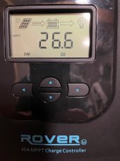
Note: When the Rover is in Bulk charge mode (Constant Current) the display will read MPPT.
Note: When the Rover is in Absorb charge mode (Constant Voltage) the display will read Boost.

Float Charge Volt(V) 13.5
The Constant Voltage charge mode Rover will transition to after the Boost Charge Time has elapsed. Rover will display Float Charge Mode.
Float is a voltage that is programmed to keep the battery topped off, but not charging, and supply power to the loads at the same time.

Boost Char Return Volt(V) 13.3
Boost charge recovery voltage(V)
When the voltage drops from float charge voltage down to to Boost Charge Return Voltage, the Rover will transition from Float voltage Charge (CV) setting to Boost charge until the Boost Charge Volt (CV) is obtained.
Rover will display Boost Charge Mode. If the voltage continues to drops further, below Boost Char Return Volt, the Rover will transition to MPPT Charge Mode which is Constant Current (bulk) charge until Boost Charge voltage level is obtained.

Over Disc Return(V) 11.0

Over discharge recovery voltage(V)
The battery voltage went below the Over Discharge Volt(V) of 10. 5v. The battery is being charged backup by the Rover at a very low rate used for batteries that have been over discharged until reaching Over Disc Return(V) of 11v.

Low Voltage Alarm(V) 10.9
Undervoltage warning voltage(V)
The voltage Rover will alarm audio and visual (Error Indicator LED and error code) when voltage is at this level.

Over Discharge Volt(V) 10.5
Voltage level that triggers Over Discharge condition

Discharge Limit Volt(V) 10
Discharge cutoff voltage(V)
Voltage the Rover will disconnect from the battery

Over Disc Delay Time(S) 10
Time Rover will wait before triggering an Over Discharge Volt level condition.

Equalize Charge Time(Min) 0
Time to equalize lead acid batteries. Not used for Lifepo4

Boost Charge Time(Min) 10
Time Rover will be in Boost charge mode as the voltage is held constant and the current tapers lower. After Boost Charge Time has elapsed Rover will transition to Float charge mode.

Equalize Charge Interval(Days) 185 (Must not be zero or Rover will stay in boost mode and never transition to float)
Number of days between equalizing lead acid batteries. Not used for Lifepo4

Temperature Compensation(DegC)0
Temp compens coefficient(mV/VC/2V)
Used to change charging of lead acid batteries due to battery temperature. Not used for Lifepo4.

Unplug temp sensor from the Renogy Rover Solar Charge Controller. It is for lead acid and not Lifepo4.

These settings should get you started. You can adjust from there.

Edit: Added the following to place all info in one message.
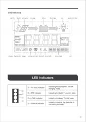
FYI

Rover Displays MPPT = Bulk Charge Mode
Rover Displays Boost = Absorb Charge Mode
Rover Displays Float = Float Charge Mode

If using the Rover USER battery settings on a typical sunny day:
When the day starts in the morning the Rover will enter MPPT charge mode (Bulk) and stay there until Boost Charge Volt(V) is obtained. The Rover will stay at Boost voltage (Absorb) for the Boost Charge Time(Min) setting. After Boost Charge Time has completed the Rover will go to Float Charge Volt(V) and stay at this voltage as long as there is enough sunlight to hold the Float voltage setting. If clouds build or if the sun starts to go down (dropping the battery voltage) the Rover will re-enter Boost mode at the Boost Char Return Volt(V). When the battery voltage goes below the Boost Char Return Volt (V) the Rover will go to MPPT charge mode. When night arrives the Rover will go into Nighttime mode with moon icon displayed and will not charge the battery. During Nighttime mode the loads will pull down the battery voltage. When morning comes the cycle repeats.
Note: The Rover should stay in MPPT charge mode (Bulk) if the battery voltage does not reach Boost (Absorb) Charge Volt.

I use the Renogy BT-1 Bluetooth Module that plugs in the Rover 40 Rs232 port.
www.amazon.com/Renogy-Bluetooth-Module-Communication-Controllers/dp/B0894SDTSL

With that Module I use the Renogy BT App loaded on my phone to program the settings and monitor the Rover 40.

UPDATE: The Renogy BT App has been removed from the Apple App Store. Use the SRNE app link below for iPhone. The SRNE app has become my preferred app for programming and monitoring the Renogy Rovers.


To program the Renogy Rover with the Renogy BT app select Settings at bottom of the screen. Once in Settings ensure Battery button is selected (not Load) & click the Read button to display the current Rover settings. Next click the Set button and then click Confirm and input default password which should be 135790123 and click Confirm. Now change the desired settings and then click the Set button. The changes should now be made. Check the settings were changed by clicking the Read button.

SRNE APP: Another App for programming & monitoring the Renogy Rover that shows promise is the SRNE Monitoring App. The App is frequently updated. This has become my preferred App. The Rovers are manufactured by SRNE so the SRNE app works on the Rovers. Downside is no manual or instructions, but the app is fairly intuitive to use.

One nice feature of this app (among many) is that the voltage scaling is displayed for the range that is programmed for the settings instead of only 12 volt range being displayed as in the Renogy BT App.
For example with the Renogy BT app setting 28.4 volt boost for a 24 volt system is entered 14.2 volts because the values must be entered in 12 volt values and are then doubled for a 24 volt system. But with the SRNE app the 28.4 volt boost is indeed entered and displayed as 28.4 volt.

If using an iPad there is another app in the Apple App Store called SRNE Monitoring(HD) that must be used that is only for the Apple iPad.

If using an Android Tablet there is another app in Google Play called SRNE Monitoring(HD) that must be used that is only for the
Android Tablet.

Note: The Renogy BT-1 Bluetooth Module that plugs in the Rover 40 Rs232 port is needed to program & monitor with the SRNE app.

Link for the iOS iPhone SRNE App

Link for the Android Phone SRNE App

Here are Pictures of My Renogy Rover 40 amp Solar Charge Controller Setup using the SRNE App on iPhone (Note: 24 Volt System)

1708438423463.png1708438501752.png1708438639352.png

Manuals for Renogy Rover & Renogy BT App
 

Attachments

  • Renogy-BT-APP Manual.pdf
    1.7 MB · Views: 23
  • Renogy Rover Li 20-30-40 Amp 12V-24V MPPT SSC Manual Ver 1_3.pdf
    2.3 MB · Views: 13
  • Renogy Rover 100 Manual Ver 1_4.pdf
    1.4 MB · Views: 1
  • Renogy Rover 60 Manual Ver 1_3.pdf
    4.5 MB · Views: 5
Last edited:
Looks like the Float Charge Volt and Boost Char Return Volt is a little to close as my preference is at least 0.2 volts. Recommend setting Float to 13.5. Low Voltage Alarm is set kind of high at 12.7 and may give you nuisance alarms and recommend setting to 12 volts. Recommend dropping Over Disc Return to 12.1 volts.

Over time you will find the best settings for your system.

Below are my settings, but note that the system never sees low voltages because the Samlex EVO inverter/charger built in transfer switch transfers load power to the grid when battery is at 12.5 volts (actually 25 volt because 24 volt system) and charges the battery. So I purposely have my low voltage setting set below the transfer setting and am not concerned with those settings. Below are my best known descriptions that may help setting your own.

Renogy Rover Solar Charge Controller with Rover BT App Settings Explained
Note: Rovers often read 0.1 to 0.2 Volts low. So at 14.2 volts actual volts Rover reads 14.0 to 14.1.
Note: Renogy Rover Solar Charge Controllers only have settings for 12 volt systems. For 24 volt systems double values and for 48 volt systems multiply by 4. So a 14 volt boost would be 28 in 24 volt system and 56 in a 48 volt system. Need Rover 60 or 100 amp for 48 volt systems.

Note: These are the best known explanations at time of writing. Some of the listed explanations may be in error. Feel free to correct.

High Volt Disconnect(V)14.5

Voltage that Rover will disconnect from battery.

Charge Limit Voltage(V) 14.1
Rover will stop charging battery at this voltage.

Equalize Charge Volt(V) 14
Voltage to equalize lead acid batteries. When using Lifepo4 set same as boost charge volt.

Boost Charge Volt(V) 14
The voltage Rover will transition from Constant Current (CC) MPPT Charge Mode (Bulk) to Constant Voltage (CV) Boost Charge Mode (absorb).

Float Charge Volt(V) 13.6
The Constant Voltage charge mode Rover will transition to after the Boost Charge Time has elapsed. Rover will display Float Charge Mode.

Boost Char Return Volt(V) 13.3
When the voltage drops from float voltage down to to Boost Charge Return Voltage, the Rover will transition from Float voltage Charge setting (CV) to (CC) charge (Bulk) until the Boost Charge Volt is obtained.
Rover will display MPPT Charge Mode which is Constant Current (bulk) charge until Boost Charge voltage level is obtained.

Over Disc Return(V) 12.0

The battery voltage went below the Over Discharge Volt(V) of 10.5v. The battery is being charged backup by the Rover at a very low rate used for batteries that have been over discharged until reaching Over Disc Return(V) of 12v.

Low Voltage Alarm(V) 11.5
The voltage Rover will alarm audio and visual (Error Indicator LED and error code) when voltage is at this level.

Over Discharge Volt(V) 10.5
Voltage level that triggers Over Discharge condition

Discharge Limit Volt(V) 10
Voltage the Rover will disconnect from the battery

Over Disc Delay Time(S) 10
Time Rover will wait before triggering an Over Discharge Volt level condition.

Equalize Charge Time(Min) 0
Time to equalize lead acid batteries. Not used for Lifepo4

Boost Charge Time(Min) 10
Time Rover will be in a Constant Voltage charge state as the current tapers toward 0 amps.

Equalize Charge Interval(Days) 185 (Must not be zero or Rover will stay in boost mode)
Number of days between equalizing lead acid batteries. Not used for Lifepo4

Temperature Compensation(DegC)0
Used to change charging of lead acid batteries due to battery temperature. Not used for Lifepo4.
This is the best explanation I've seen, thanks it really helps out. It was the Over Disc Return I was most interested in....I had a feeling when I set that it was on the high side. Looks like I'm getting there with the settings....this is a great forum.
 
Attached are the Manuals for Renogy Rover 40 amp solar charge controller and the Renogy BT app. First look at the manual for the Renogy BT App. Verify the Renogy BT app is in use. There are other Renogy apps that do not work the same as you mentioned the Renogy DC Home.

The parameters that were listed in the previous message should all be able to be modified.

To program the Rover 40 with the Renogy BT app select Settings at bottom of the screen. Once in Settings ensure Battery button is selected (not Load) & click the Read button to display the current Rover settings. Next click the Set button and then click Confirm and input default password which should be 135790123 and click Confirm. Now change the desired settings and then click the Set button. The changes should now be made. Check the settings were changed by clicking the Read button.

If still not able to program all the settings of the Rover 40 using the Renogy BT app, try Restore the Rover 40 to Factory Settings by clicking the Info button at the bottom of the screen in the Renogy BT app and then click Restore to Factory Default.

Another item to try is remove all Renogy apps from your phone and install only the Renogy BT app. Reboot the phone before reloading the Renogy BT app.

Hope this helps...
Dynoman,
your post was very helpful to me in figuring out how to set the parameters of my Rover 40 controller to work correctly with a new Chins battery. You deserve a big thank you for your informative post.
 
So, @Dynoman , do I set the numbers for a 24 volt system at 12 volt levels and the controller doubles it? Or, do I set at 24 volt numbers?

I haven‘t hooked up my controller yet so I haven’t seen the settings in the app.
 
So, @Dynoman , do I set the numbers for a 24 volt system at 12 volt levels and the controller doubles it? Or, do I set at 24 volt numbers?

I haven‘t hooked up my controller yet so I haven’t seen the settings in the app.

If you have a Renogy Rover Solar Charge Controller (SCC) and are running a 24 VDC system, the settings entered are for a 12 VDC system, but the output will be 24 VDC. The Rover only has 12 volt parameter settings.

The Rover needs to be set to auto-scale for the detected voltage of the battery (default) or can be forced to 24 Volts.

Once the Rover is set for 24 Volts the parameter settings are entered for 12 Volts and the Rover doubles the settings. For example setting a 14.1 boost voltage will set the boost voltage to 28.2 with a 24 volt battery connected to the Rover.

Hope that helps...
 
This is the best explanation I've seen, thanks it really helps out. It was the Over Disc Return I was most interested in....I had a feeling when I set that it was on the high side. Looks like I'm getting there with the settings....this is a great forum.

To keep the batteries balanced...

When the Rover 40 is in boost, watch how low of a value the amps taper to going into the batteries. Probably best to watch the amps on the battery monitor. If the amps going into the batteries don't taper toward zero amps (although amps should not reach zero) the boost time should probably be increased. Some suggest the amps should taper to 4% of total ah (400 x .04 = 16 amps), but that is subjective and depends on the system.

Bottom line with the system in full sun mid part of the day and the Rover transitions from MPPT Charge Mode to Boost Charge Mode there should be some significant tapering of the amps before the boost ends and transitions to Float. If the amps don't really decrease much in boost, increase the Boost Charge Time by 10 minutes and watch the next boost cycle. Repeat as necessary until the desired taper is achieved.

If the BMS of one or more batteries goes into overvoltage and disconnects reduce the boost voltage.

Over time may find that a shorter boost works most of the time with an occasional longer boost time when the batteries are truly balanced.

If the 4 Chins batteries are or get significantly out of balance from each other they should be fully charged up individually. Occasionally this may have to be done.

Usually before the batteries are connected into a battery bank all batteries are fully charged individually and then connected to form the battery bank.
 
Last edited:
Looks like the Float Charge Volt and Boost Char Return Volt is a little to close as my preference is at least 0.2 volts. Recommend setting Float to 13.5. Low Voltage Alarm is set kind of high at 12.7 and may give you nuisance alarms and recommend setting to 12 volts. Recommend dropping Over Disc Return to 12.1 volts.

Over time you will find the best settings for your system.

Below are my settings, but note that the system never sees low voltages because the Samlex EVO inverter/charger built in transfer switch transfers load power to the grid when battery is at 12.5 volts (actually 25 volt because 24 volt system) and charges the battery. So I purposely have my low voltage setting set below the transfer setting and am not concerned with those settings. Below are my best known descriptions that may help setting your own.

Renogy Rover Solar Charge Controller with Rover BT App Settings Explained
Note: Rovers often read 0.1 to 0.2 Volts low. So at 14.2 volts actual volts Rover reads 14.0 to 14.1.
Note: Renogy Rover Solar Charge Controllers only have settings for 12 volt systems. For 24 volt systems double values and for 48 volt systems multiply by 4. So a 14 volt boost would be 28 in 24 volt system and 56 in a 48 volt system. Need Rover 60 or 100 amp for 48 volt systems.

Note: These are the best known explanations at time of writing. Some of the listed explanations may be in error. Feel free to correct.

High Volt Disconnect(V)14.5

Voltage that Rover will disconnect from battery.

Charge Limit Voltage(V) 14.1
Rover will stop charging battery at this voltage.

Equalize Charge Volt(V) 14
Voltage to equalize lead acid batteries. When using Lifepo4 set same as boost charge volt.

Boost Charge Volt(V) 14
The voltage Rover will transition from Constant Current (CC) MPPT Charge Mode (Bulk) to Constant Voltage (CV) Boost Charge Mode (absorb).

Float Charge Volt(V) 13.6
The Constant Voltage charge mode Rover will transition to after the Boost Charge Time has elapsed. Rover will display Float Charge Mode.

Boost Char Return Volt(V) 13.3
When the voltage drops from float voltage down to to Boost Charge Return Voltage, the Rover will transition from Float voltage Charge setting (CV) to (CC) charge (Bulk) until the Boost Charge Volt is obtained.
Rover will display MPPT Charge Mode which is Constant Current (bulk) charge until Boost Charge voltage level is obtained.

Over Disc Return(V) 12.0

The battery voltage went below the Over Discharge Volt(V) of 10.5v. The battery is being charged backup by the Rover at a very low rate used for batteries that have been over discharged until reaching Over Disc Return(V) of 12v.

Low Voltage Alarm(V) 11.5
The voltage Rover will alarm audio and visual (Error Indicator LED and error code) when voltage is at this level.

Over Discharge Volt(V) 10.5
Voltage level that triggers Over Discharge condition

Discharge Limit Volt(V) 10
Voltage the Rover will disconnect from the battery

Over Disc Delay Time(S) 10
Time Rover will wait before triggering an Over Discharge Volt level condition.

Equalize Charge Time(Min) 0
Time to equalize lead acid batteries. Not used for Lifepo4

Boost Charge Time(Min) 10
Time Rover will be in a Constant Voltage charge state as the current tapers toward 0 amps.

Equalize Charge Interval(Days) 185 (Must not be zero or Rover will stay in boost mode)
Number of days between equalizing lead acid batteries. Not used for Lifepo4

Temperature Compensation(DegC)0
Used to change charging of lead acid batteries due to battery temperature. Not used for Lifepo4.
Thank you for this info. I am using SOK lithium Batteries.
would that make a big difference? This is under USER settings, correct? I really like how you explained each setting. This is awesome, I have looked all over for something like this....
 
Thank you for this info. I am using SOK lithium Batteries.
would that make a big difference? This is under USER settings, correct? I really like how you explained each setting. This is awesome, I have looked all over for something like this....

Yes, the settings described are with the USER settings with the Renogy BT app. It would seem the SOK Lifepo4 would be similar since it is a Lifepo4 battery. The settings should be a good place to start although there may be some small differences possibly due to different BMS. Suggest looking at the SOK Lifep04 spec sheet.
 
Glad to hear the fuse & breaker are ordered. Suggest they be Installed ASAP.

The 2 gauge wire at the lower loads that are running on the system should not get warm. If or when large loads are placed on the inverter for a time the 2 gauge wire will heat up. Nothing wrong with the wire getting warm as long as not hot when higher currents are flowing. The heat felt in the wire are losses though. A bigger size wire would be better, but the way the system is currently used 2 gauge is good. If system demand increases significantly and the wire gets hot 1/0 gauge wire would be a good choice.

The 8 gauge wire was getting warm at near 40 amps from the Rover 40, but that was OK. 8 gauge wire at 2 feet long with 40 amps is only 0.5% loss in heat. Nothing wrong with the 6 gauge and it will have less losses. Bigger wire is usually better. If my recollection serves me right, the Rover 40 will only accept 8 gauge as the largest wire. Might have to cut a few strands of wire off on the stripped ends to get the 6 gauge wire in the Rover 40 clamp terminals, but that is OK and really little to no loss. Check that no stray strands of wire are out of the Rover 40 terminal clamps with the 6 gauge wire.

If you find the 6 gauge wire is more pain than it is worth the 8 gauge wire is good for the Rover 40.
Update, got that 200 amp fuse and circuit breaker hooked up. Question: Got my float set to 13.4v but once the controller comes off boost it hangs around 13.9v for most of the time throughout the day until I turn on my power. Can't figure that out.
 
Update, got that 200 amp fuse and circuit breaker hooked up. Question: Got my float set to 13.4v but once the controller comes off boost it hangs around 13.9v for most of the time throughout the day until I turn on my power. Can't figure that out.

Glad to hear the fuses are in place as they are very important for safety in any solar system especially with Lifepo4 batteries.

The Renogy Rover float value of 13.4 is good.

After the batteries have just been essentially fully charged with a boost mode of 14.3 volts and without a load pulling current the the batteries will settle at about 13.8 volts. Lifepo4 cells will settle around 3.45 to 3.5 volts per cell after being fully charged. Each 12 volt battery has 4 cells.
4 x 3.45 = 13.8 volts.

Once power to the loads is turned on and current flows the batteries should settle around the float value setting of 13.4v in the neighborhood of 13.4 to 13.6 actual volts (measured with good volt meter) as the Rover supplies the power to the loads as long as there is enough sunshine.
 
Post to describe Renogy Rover 40 amp MPPT Solar Charge Controller Modes:

The best way to know what mode the Renogy Rover 40 amp SCC is in is to look at the Main Page Display using the up/dn arrow keys. See attached pictures.

One picture shows the Rover 40 Main Page Display in MPPT Mode.

The other picture is page 22 of the manual. With the Rover 40 in MPPT mode the PV Array Indicator LED (Shown in Manual Page 22 Picture) is solid. With the Rover 40 in Boost the LED will flash on/off steady. With Rover 40 in Float the LED will quick flash on and then off.

Again the best way to know what mode the Rover 40 is currently operating in is to look at the Main Page Display. Notice in the attached picture of page 22 of the manual it list the modes that the Rover 40 can display.
 

Attachments

  • Renogy Rover 40 Main Screen Page 22 Manual.JPG
    Renogy Rover 40 Main Screen Page 22 Manual.JPG
    63.9 KB · Views: 36
  • Rover 40 Main Screen Picture.jpg
    Rover 40 Main Screen Picture.jpg
    140 KB · Views: 34
Last edited:
Renogy Rover Solar Charge Controller with Rover BT App Settings Explained

Thanks for this detailed post. So are you saying that some of these settings can't be adjusted without the BT module and through their app? We have the Rover 30 (looks exactly like yours except only 30A output) and I know some of these settings are adjustable on the unit itself, but since our entire system is dismantled at the moment, I can't confirm. I'd hate to have to get the BT module just to make some of these changes.

When we put the system back together, it will be with a 12v lifepo4 battery and I'm gathering infos on how to best charge them.

Have not programmed the Rover 40 manually because it came as a package with the BT-1 module.

This is an attempt to try and translate what is in the manual if programming using the buttons on the Rover itself.
over-voltage Warning 14.5
Equalization Voltage 14.1
Boost Voltage 14.1
Float Voltage 13.6
Boost Return Voltage 13.2
Under Voltage Warning 10.9
Under Voltage Recover 11
Low Voltage Disconnect 10
Low Voltage Reconnect 11.2
Equalization Duration 0 Hrs.
Boost Duration 1 Hrs.

Again this is an estimate and could be in error since going by interpretating the manual. One thing that it shows is the Boost Duration is only programmable in hours if reading the Rover manual correctly. With BT-1 10 minute intervals are available. I also don't see a charge limit voltage which is a valuable setting. My take is the USER settings available shown in the manual are for Lead Acid batteries and not Lifepo4.

Another nice feature of the BT-1 is the ability to monitor Realtime the Rover SCC. Without it one has to flip between the different screens using the buttons. Not a big deal but its nice to just see everything on one screen on the phone remotely as long as in BT range.

As it can probably be seen there is a biased toward the BT-1 module and Renogy BT App on my part.

The Renogy Rover SCC probably functions just fine without the BT-1 module and Renogy BT App, but I don't know since never used it that way.
 
Last edited:
Have not programmed the Rover 40 manually because it came as a package with the BT-1 module.

This is an attempt to try and translate what is in the manual if programming using the buttons on the Rover itself.
over-voltage Warning 14.5
Equalization Voltage 14.1
Boost Voltage 14.1
Float Voltage 13.6
Boost Return Voltage 13.2
Under Voltage Warning 10.9
Under Voltage Recover 11
Low Voltage Disconnect 10
Low Voltage Reconnect 11.2
Equalization Duration 0 Hrs.
Boost Duration 1 Hrs.

Again this is an estimate and could be in error since going by interpretating the manual. One thing that it shows is the Boost Duration is only programmable in hours if reading the Rover manual correctly. With BT-1 10 minute intervals are available. I also don't see a charge limit voltage which is a valuable setting. My take is the USER settings available shown in the manual are for Lead Acid batteries and not Lifepo4.

Another nice feature of the BT-1 is the ability to monitor Realtime the Rover SCC. Without it one has to flip between the different screens using the buttons. Not a big deal but its nice to just see everything on one screen on the phone remotely as long as in BT range.

As it can probably be seen there is a biased toward the BT-1 module and Renogy BT App on my part.

The Renogy Rover SCC probably functions just fine without the BT-1 module and Renogy BT App, but I don't know since never used it that way.
Thank you for your helpful replies here on the topic. The tip that these Renogy Rover MPPTs tend to be reporting too low by 0.1 to 0.2v is very helpful too.

I’m still learning about charging batteries in general. For lifepo4, what is the advantage to a short (10 minute) absorption time?
 
Thank you for your helpful replies here on the topic. The tip that these Renogy Rover MPPTs tend to be reporting too low by 0.1 to 0.2v is very helpful too.

I’m still learning about charging batteries in general. For lifepo4, what is the advantage to a short (10 minute) absorption time?

The way I understand it, one of the best indicators the battery is fully charged (or nearly fully charged) is each cell in the battery reaches 3.5 to 3.55 volts and hold it there in Constant Voltage charging mode (Boost, Absorb) until the charging current (Tail Current) drops to 4 or 5%. Tail Current is expressed as a percent of the battery Amp Hour (AH) rating. A 200 AH battery tail current of 5% would be 10 amps (200 x .05 = 10).

A 12 volt Lifepo4 battery has 4 cells (4 x 3.55 = 14.2 volts). When the battery charging goes from Constant Current (Bulk) to Constant Voltage (Boost) at 14.2 Volts the battery voltage is held at about 14.2 volts until the tail current flowing into the battery is about 4 or 5% before transitioning to Float. It is probably OK to leave in boost for 10 minutes or so past reaching the tail current, but only being able to adjust in hours the Boost time is not good for Lifepo4 cells. Leaving a Lead Acid battery in Boost for an hour or hours is OK, but not Lifepo4 in my opinion.

Typically my system stays in boost for only 10 to 20 minutes around 28.5 volts (24 volt system).

The only time my system will stay in boost for longer period of time is if the cells need significant top balancing, but that is rare and only increase the time to 30 or 40 minutes.

One could lower the boost voltage to a value a little over float voltage and stay in boost for longer times to obtain a near fully charged battery before float, but that is not how my system is programmed. I prefer to fully charge my cells as quickly as possible. This becomes more important in the winter in my area with limited sun and significant clouds.

That's my 2 cents worth...
 
Last edited:
The way I understand it, one of the best indicators the battery is fully charged (or nearly fully charged) is each cell in the battery reaches 3.5 to 3.55 volts and hold it there in Constant Voltage charging mode (Boost, Absorb) until the charging Tail Current drops to 4 or 5%. Tail Current is the percent of the battery current flowing into the battery as a percent of the Amp Hour (AH) rating of the battery. A 200 AH battery tail current of 5% would be 10 amps (200 x .05 = 10).

A 12 volt Lifepo4 battery has 4 cells (4 x 3.55 = 14.2 volts). When the battery goes from Constant Current (Bulk) to Constant Voltage (Boost) at 14.2 Volts the battery voltage is held at 14.2 volts until the tail current is about 4 or 5% before transitioning to Float. It is probably OK to leave in boost for 10 minutes or so past reaching the tail current, but only being able to adjust in hours the Boost time is not good for Lifepo4 cells. Leaving a Lead Acid battery in Boost for an hour or hours is OK, but not Lifepo4 in my opinion.

Typically my system stays in boost for only 10 to 20 minutes around 28.5 volts (24 volt system).

The only time my system will stay in boost for longer period of time is if the cells need significant top balancing, but that is rare and only increase the time to 30 or 40 minutes.

One could lower the boost voltage to a value a little over float voltage and stay in boost for longer times to obtain a near fully charged battery before float, but that is not how my system is programmed. I prefer to fully charge my cells as quickly as possible. This becomes more important in the winter in my area with limited sun and significant clouds.

That's my 2 cents worth...
Thank you, this is really helpful. I’m slowly starting to understand charging for lithium batteries and your examples help a lot.
 
Back
Top