diy solar

diy solar

Growatt SPF very high idle power

Can someone confirm this?... I am reinstalling my system because i will install my own diy battery to my Growatt, but my battery is not finished yet.
I have connected the inverter input to the grid and the output to my home loads. I Measured (at night) with a clamp ampere meter to the input and measure around 3 amp consumption (690w) At the output i measure 1,7 amp (391w) the visual power on the app are soft is 344w input and 337w output ???
 
Clampeter read in alternating current is misleading if you wand to know the power.
You red the current.
Voltage x Current formula for P is valid for ACTIVE POWER.

The inverter consumes reactive power.
For the reactive power the formula is Current x Voltage x cosFI (power factor)
 
Clampeter read in alternating current is misleading if you wand to know the power.
You red the current.
Voltage x Current formula for P is valid for ACTIVE POWER.

The inverter consumes reactive power.
For the reactive power the formula is Current x Voltage x cosFI (power factor)
Agree but can you also explain why i measure almost the double of it (input - output) there is also a VA power reading on the growatt so....
 
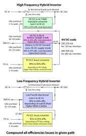
The HV DC to battery converter must be operating to supply AC input charging or PV SCC HV DC charging to batteries. The SCC controller also consumes overhead power although it is much lower than the HV DC to battery converter.

The unit uses battery power to supply both these circuits overhead operational power. It provides a reliable source compared to variable PV power. It makes things a lot simpler than handling repeated SCC startup collapses when PV power is too low to support overhead power required.

The HV DC to battery converter is about 60-75% of the normal inverter idle consumption and is the dominate overhead power.

The firmware is not smart enough to figure out when overhead power exceeds the yielded available PV power and stop the net battery bleeding loss.

If you have three units in parallel, then you have three times the overhead power. I would expect three times a single unit's overhead would be greater than 115 watts so you likely have at least a little PV power to offset some of it. You likely need about 130-140 watts of PV power to breakeven, zero'g out battery current.
Inverter power paths.png
 
The HV DC to battery converter must be operating to supply AC input charging or PV SCC HV DC charging to batteries. The SCC controller also consumes overhead power although it is much lower than the HV DC to battery converter.

The unit uses battery power to supply both these circuits overhead operational power. It provides a reliable source compared to variable PV power. It makes things a lot simpler than handling repeated SCC startup collapses when PV power is too low to support overhead power required.

The HV DC to battery converter is about 60-75% of the normal inverter idle consumption and is the dominate overhead power.

The firmware is not smart enough to figure out when overhead power exceeds the yielded available PV power and stop the net battery bleeding loss.

If you have three units in parallel, then you have three times the overhead power. I would expect three times a single unit's overhead would be greater than 115 watts so you likely have at least a little PV power to offset some of it. You likely need about 130-140 watts of PV power to breakeven, zero'g out battery current.
View attachment 131068
This enplanes when I increase the load the efficiencies are a lot better, is this only a growatt issue?
I have bought a second one a while ago, still new, so I'm going to do some test on this one in another environment and playing with some settings.
 
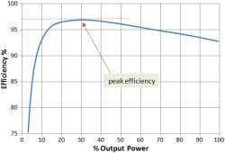
Typical efficiency curves look like attached graph.

At low load on inverter the fixed idle overhead power dominates which is mostly the high frequency switching of the power switching devices gate input drive power and some loss due to PWM filtering reactive load current on inverter. At high AC load, the IR loss of MOSFET's, IGBT's, and wiring dominates.

Most spec sheets show the best efficiency number around 30% inverter loading,

When you see a spec sheet with 'CEC' rated efficiency, it is a weighted average at various load points,

4% of time at 10% loading.
5% of time at 20% loading.
12% of time at 30% loading.
21% of time at 50% loading.
53% of time at 75% loading.
5% of time at 100% loading.


Typical inverter efficiency.png
 
Last edited:
Thanks @RCinFLA, your block diagram in post #24 above really helped me understand the inherent inefficiencies of the high frequency/AIO inverter topology. I might be losing more power than I realise... Time to do some more testing!
 
The entire system efficiency on long term use (one year now) is ~ 75%

I mean 75% from the Solar energy reached to loads by 2 ways:
- solar > mppt > DC/AC conversion > ACout
- solar > mppt > DC/DC > battery.... and battery > DC/AC > ACout

Solar input measured by the inverter.
AC out measured by ShellyEM.
75% is low but not and unusual number. Panels have an efficiency of 90..97% depending on the heat of the solar cell, The inverter runs between 93..97%, Wire conductance is 98% effective, Panel faulting is between 90..95% Multiply these numbers, and you know what you can expect.
 
Consider switching your always on loads to DC power and shut down the Growatt to save on idle loss. My whole tech room setup uses 59 watts DC direct from my 44V battery and runs my PC, DVR, 1x IP cam, 2x LED PC monitors, Fiber to LAN / Network switch, Audio amplifier, 2x LED lights. All running on same power that single Growatt uses for idle.
 
I think that what really matters is net system efficiency. EG: much energy ultimately ends up being used by loads. Energy produced/Energy used

Also I'm confused (dare I say disagree?) with his comments about AIO being more efficient because they use the solar energy directly for loads versus a non AIO set up with a separate CC and inverter that has to charge and discharge the batteries. That is not accurate. When the CC's and inverters are all on the same DC buss the inverters will use the solar energy directly before batteries are charged.
correct, well seen
 
75% is low but not and unusual number. Panels have an efficiency of 90..97% depending on the heat of the solar cell, The inverter runs between 93..97%, Wire conductance is 98% effective, Panel faulting is between 90..95% Multiply these numbers, and you know what you can expect.
I am talking about the input values inverter measures (the power on MPPT input, integrated results energy) and the total energy which came out (from inverter or other other energy measuring device like shellyEM).
So the panel efficiency/faults and wire loss does not count.
It is about using energy "directly" MPPT>bus400V>DC/AC and through the battery (MPPT>DC400/DC48>batteryCharge + Battery>DC48/DC400>DC400/AC230).
Additionally the inverter has its auxiliary power consumption 60-70W which is included in the 25% yearly loss (~640kwh).
My system is 6kwp/5kw/15kwh.
OK i got it.
 
Back
Top