diy solar

diy solar

1.5 Watt panel supplying power coffee grinder for my coffee grinder every morning but I need a small controller

If we are going for cheap contest i think ill win. Im budget minded but hopefully someone can beat me.


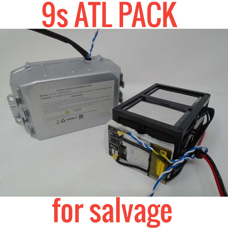
Pre-made battery, with bms @ 32 volts. As stated in the description people are using the bms and leaving 2 cells out. Pick the good cells and run it in a 12v pack or rewire to make a larger pack if wanted or needed. $5 is about as cheap as it gets and its already in a fireproof container. You will spend more money on the screwdriver to open the box than the battery and nothing else is needed.

Edit: might not ship outside of the US though.
 
I just took another look to verify. Another correction. 230 CCA. Not 240 as reported. Guessing a little over 30 ah. 230/7.25=31.724. The constant , 7.25 being used to derive approximate ah from CCA.

Yes, that sounds like a typical group U1 mower battery. About 30-35AH. You are about 75% charged at 12.4v, not bad for a few days of clouds with that little panel.
 
I'm surprised to leard that the charge controller is using any power at night. Is there a backlit display?
My Chinese charge controller for my 12v lead acid battery has an LCD display with a backlight. I can't figure out how to turn off the display as I'm not familiar with the pinouts of the display. Like the OP, I only have a problem with the 12v battery slowly declining during the winter, we have below average winter sun for my Michigan town.
 
Last edited:
but I am considering buying a manual hand-grinder - have you considered that?
I have a manual hand grinder with a ceramic grinding cone, I love it. I have a lot of control over the grind, the ceramic grinders are the best. And it's a lot cheaper than a $100 invertor! It was about $35usd.
 
I left the PV panel connected yesterday after grinding. A short recovery period later it was reading 12.4 volts. Left it connected overnight also because the forecast was for a sunny day, today. The battery reading was 13 .1 volts, before grinding, this morning. Did the grind and gave it a recovery period of about 5 minutes. Reading 12.6 now.

I know I'm in the ball park but I am trying to figure out how to stop the overnight, small but inexorable discharge I have now. Besides manually disconnecting the PV panel every evening as it gets dark outside. Also other times I have seen 16 or 17 volts and it alarms me somewhat. The more direct angle of the low sun seems to push a LOT more out of the PV panel than the summer sun does, during longer days. The panel is hung vertically.

So far it seems there is no charge controller available that do not offer parasitic drain low enough for this tiny PV panel to overcome except the circuitry in side it whcih negates any charging when it's cloudy outside. That doesn't leave me much choice.

I'm considering a piggy-back circuit with a mechanical latching relay and it's own battery power supply. I know there are relays that do not require power to maintain a state of current flow or to maintain the off state. A momentary pulse toggles them from one state to the other on/off or off/on.

The PV panel would then be responsible for keeping a very small battery (for the relay) charged as well as the 30 ah Lead Acid battery for the grinder. That seems to be a possibility. The relay would be controlled by a circuit that sensed voltage and acted accordingly. The small battery powering the relay would also power the sensing circuit.

Does anything like my latest idea exist at any scale anywhere ? Yes I already knew it would be relatively cheap and easy to use larger everything but for reasons I have already stated that is not what I am after. Manually grinding coffee beans is nice but that is not what I'm am attempting to do here.

For the record, what is the smallest PV panel, charge controller, battery and wiring that is considered to be practical these days ? I already have seen listed here, a number of small battery and charge controller options. What about the PV panel and wire ? Physical dimensions, please.
 
it was reading 12.4 volts. Left it connected overnight also because the forecast was for a sunny day, today. The battery reading was 13 .1 volts, before grinding, this morning.

Where is this voltage drop at night you are talking about? 13.1v in the morning, what's the problem?

I am trying to figure out how to stop the overnight, small but inexorable discharge I have now. Besides manually disconnecting the PV panel every evening as it gets dark outside.

We told you 5 times, that's what the diode (LED) was for (that you bypassed).

Also other times I have seen 16 or 17 volts and it alarms me somewhat. The more direct angle of the low sun seems to push a LOT more out of the PV panel than the summer sun does, during longer days. The panel is hung vertically.

None of that makes any sense. Why is the panel mounted vertically?

Have you done any amperage or draw tests with your Fluke meter yet? All I see is you testing voltage of the panel, which is almost meaningless. I can hold my little 1w solar panel up to an indoor light and it will output 22v, but it has almost no amperage...so it's meaningless.
 
Last edited:
So you could get a 20-30 watt panel and a high quality victron PWM controller, this will be overkill for your usage. For the same money you might as well just buy a 30-50 watt panel the same controller you were going ro buy anyways. If will always be full, if its not your battery has issues.

Similar example to what you are doing is found on automatic gate openers. I have done quite a lot of work on these and they run 10 watt panels on 20ah SLA batteries without charge controllers or anything in between except an anti reversing diode. Fuses are rated for 15 amps and they probably use as much as your little grinder. They also open and close multiple times a day. This level of voltage wont really hurt lead acid at low wattage. Your battery will pull down the voltage coming from the panel as well. You can re design everything if you like but if you just get that battery to float all day it will be happiest.
 
<snip>
So far it seems there is no charge controller available that do not offer parasitic drain low enough for this tiny PV panel to overcome except the circuitry in side it whcih negates any charging when it's cloudy outside. That doesn't leave me much choice.
It appears you want to overlook or don't understand the zener solution. Think about trickling water into a bucket until it overflows. If you want only a certain level in the bucket, drill a large enough hole at that level and the bucket will never fill beyond that hole. 14.4v zener will stop the charging without any other control.
 
I'm considering a piggy-back circuit with a mechanical latching relay and it's own battery power supply.

For something with so little power/draw I think you are way overthinking things. If you really wanted to, I'd research using a transistor instead of a relay. It can be triggered on by the panel voltage itself, I'd assume. Maybe it could be powered by a photodiode, but using the panel would make more sense if possible.
 
In lieu of a photgraph of the circuit inside my PV panel, here is a link to youtube that provides some more insight into the blue LED and circuitry inside my 1.5 Watt PV panel:


I cut the wire to the blue LED as shown in the video. As it turns out I also tried the buck convertor as shown in the video. I had forgotten about getting it and trying it. It also caused to much of a voltage drop and would not charge the battery at the end of the 50 foot long wires I have between the PV panel and the battery.

I have the PV panel hanging vertically due to cosmetic appearances and I am not going to change that. I'll again I ask, what are the physical dimensions of what would be considered an adequate PV panel ? It will be hanging vertically as well. I undersatnd causing the oblique angle to the sun makes it unable to work at full capacity.

I would like to measure amperage but I do not know how to in this system. I understand the less cloudy it is, the better for best case results but ...

1. Do I simply put the ammeter in series between the two leads from the PV panel to measure maximum power it can produce ?
2. Do I instead, put the ammeter in series on one lead from the panel to the battery terminal to measure how much is going into the battery ?

I can probably dig up a separate diode from some spare parts I have. I'll have to order a Zener however. I assume the voltage drop will prevent any power flow from this small charger but for the sake of everyone suggesting it, I suppose it needs to be done. I'll look into placing an order for a 13.5 V zener, although I honestly feel like it will cause too much voltage drop and resultant loss of power left over to charge the battery enough.

3. Does it matter what type or size diode ? I assume it needs to be able to handle at least enough amps to cover the 1.5 watts but no more ?
4. Will a diode rated for higher amperage casue more voltage drop ?

When it was getting dark yesterday the battery voltage read 13.1. This morning it was down to 11.7 and cloudy out again.
 
I came across this little MPPT board. From the reviews:

"One interesting point is that the IC is powered by the panel and not the battery so at night it is powered down and the unit does not pull any significant standing current from the battery. In this respect it is a big improvement on the controller I used previously which drew 20mA day and night from the battery."

 
To measure do exactly as the guy did in the video you provided. One lead to neg one to pos from the panel. Its at 1:30 in the vid. Panels are not rated by dimensions so you are equivilently asking what color is required to make a plane fly. Thats a joke but honestly it could vary widely. You could buy a 15 watt solar panel from harbor freight that is the same size as a 40 watt quality monocrystaline from a reputable brand. I guess if you got something with 2 square feet you would be ok.
 
<snip>

I can probably dig up a separate diode from some spare parts I have. I'll have to order a Zener however. I assume the voltage drop will prevent any power flow from this small charger but for the sake of everyone suggesting it, I suppose it needs to be done. I'll look into placing an order for a 13.5 V zener, although I honestly feel like it will cause too much voltage drop and resultant loss of power left over to charge the battery enough.
<snip>

I think you are failing to understand the circuit. The zener is not in series with the panel and the battery. You really need to understand the circuit and if you don't, then ask. The zener is across the battery poles to short anything over the zener value. It needs to be sized so the watts are greater than the power it will have to short. I suggested a 5 watt previously. Note, if you put it in backwards it will go up in smoke the instant you connect it to the battery. Vout is your battery. Rs is not needed if the zener watts is much higher than your Vin watts. With a 14.4v zener nothing happens until the battery tries to go over 14.4v and then the zener takes all the extra power to 0V.

Reference page.
zener-regulator.png
 
Another note on the Zener.....if you separate your panel from the battery, connect the zener across the panel leads. Connected one way, it will short the panel to something like 0.6 volts. That is not what you want when you connect to the battery, but without the battery, the zener should be able to short the panel. Connect the zener the other direction and it will clamp the panel to the zener's voltage. like 13.5 or 14.4, or what ever the zener volt rating is. When you have it connected like this you know it is correct and you can then connect the battery as always. if the battery is lower volts than the clamped output, the battery will suck the panel voltage down to the battery voltage and it will start charging up. But it will then never get above the zener voltage.
 
To measure do exactly as the guy did in the video you provided. One lead to neg one to pos from the panel. Its at 1:30 in the vid.
Battery in the el-cheapo meter died. The Fluke says about 0.09 amps at 21.9 volts measuring between the two PV panel leads with nothing else in the circuit.

PV panel is still hanging vertically., Sun is shining brightly, all morning. Battery was at 12.7 & before grinding, then down to 12.2 after a recovery 5 minutes rest. Now reading 13.7. About 4 hours after grinding. I left it disconnected from the PV panel until I need to use it tomorrow morning.
 
I think you are failing to understand the circuit.
You know the feeling you get when you finally understand what someone has been trying to tell you for a while and you just didn't get it ? You were correct DThames. That diagram made the difference. I was forgetting that Zeners are used in parallel. I have always understood their usefulness as I have had several older motorcycles that used them the same way. Of course that should work. I'll order up a 5 watt one ASAP !


Thank you for your patience.

It still does not take care of the nightly discharge. For now, every afternoon I'm disconnecting the PV panel leads from the battery ... when I remember to.

I'll follow up when I have the Zener in the circuit and can do some more readings. Still worried about the nightly discharge however. Which is the topic of this thread after all.

Maybe a simple timer to do the disconnect/reconnect daily to prevent nightly discharge. Also along with the Zener to prevent overcharging. Maybe that will be the ultimate answer until a better solution is figured out. The tiny amount of available current from this PV panel does fringe on the unusable but so far it has been giving me some usefullness. Daily.
 
OK, I have some news to report. Voltage this morning was 12.9v before I turned on the inverter. A couple of hours after grinding my coffee it's at 12.7v.

The difference is, the sun is very bright today. Also there is a brand spanking new MPPT Solar Panel Controller Battery Board as suggested by SolarRat. It seems to be working as far as charging the battery is concerned.

I was concerned that any amount of electronics would dimish the output of the PV panel enough to prevent it from fully charging the battery. Apparently this thing is putting in some charge when the PV panel is in full and nearly direct sunlight. Time will tell if it charges fully or not. Also if it will prevent overcharging and/or nightly discharge. If it does all 3, it will be the answer I was looking for.

I burnt out the first board by connecting the battery backwards. When I explained the incorrect info on their diagram, I got an immediate refund. I ordered another and it arrived yesterday.

!NOTE! This diagram is mislabled at the Battery lead clamps. battery+ is the bottom clamp. Not the 2nd one up, as shown below.

MPPT Solar Charge Controller.png
 
I doctored the diagram so it's correct below.
 

Attachments

  • MPPT Solar Charge Controller.jpg
    MPPT Solar Charge Controller.jpg
    176.9 KB · Views: 5
So you have control over the MPPT and the final charge to voltage but no control of the amps?
 
DThames, I have no idea what I have control over. I'm not sure I have this thign setup correctly. I know it's wired properly now, at least.

The instructions are very hard for me to figure out. There is a trimpot to adjust MPPT voltage. There is another trim-pot to adjust maximum battery voltage. one LED is steady red when it's charging. The LED turns steady blue and has a small red portion that flashes when something happens. Not sure what that signifies however.

The best I can make out of the instructions for adjusting it had me do the following. With the PV panel in full direct sunlight and connected to the MPPT board, I turned the MPPT trimpot counterclockwise until the LED turned blue with flashing red. Then I turned the MPPT trim-pot until the LED turned steady red.

Next I connected the voltmeter to the battery connections on the MPPT board. Then I turned the battery voltage trim-pot to 14.5 volts and connected the battery. The LED is steady red which is supposedly signifying it is charging the battery.

The PV panel waas in full direct sunlight also yesterday when I installed the MPPT board and made the trim-pot adjustments. The battery Voltage was reading 12.6 volts before and afterwards.

At night the LED was off. Battery voltage this morning is reading 12.5 volts. It doesn't seem to have drained the battery overnight but it also does not seem to have charged ip ut any higher than it had been after several cloudy days in a row.

I'm going to try to find better directions on adjusting this MPPT board. Maybe my adjustments are all wrong. One set of instructions from a person who has used this board started out using a power supply and 1st setting the MPPT trim-pot voltage to something a little lower than the panel is providing. 18 Volts. When I did that the LED turned steady blue with the red flashing. Then, using a capacitor in place of the battery to set the maximum charge voltage. 14.5 Volts. Then going back to the MPPT Tim-pot and making a final adjustment but I couldn't understand adjust it to what ?

Any suggestions for a different adjustment procedure I could try. I don't have a power supply to use in place of the PV panel which is putting out about 21 Volts in direct full sunlight.
 
Back
Top