diy solar

diy solar

120/240 split phase amp confusion

DefyTheGrid

New Member
Joined
May 14, 2021
Messages
23
Location
Utah
Hey all,

I have a question that needs resolution and I'm sure y'all can help.

My home has a 200a panel which feeds the house with electricity. The wire is let's say 4/0 gauge copper wire.

When I look up the amp rating of 4/0 wire, I find that it's rated for 230 amps. What confuses the heck out of me is why I have two lines and one neutral that are all 4/0 wire. Because there's two lines, does that mean my house can use 400a at a time without tripping the 200a (240v) breaker? Does each line allow 200a or 100a or is it variable?

I guess you can say I'm a bit confused, and it probably stems from my lack of knowledge of how 120/240 split phase works and how split phase gets away with only one neutral wire... Any help would help me get some sleep :)

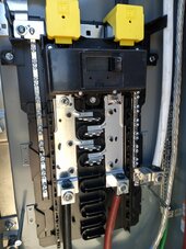
Here's a pic of my panel just for fun.
 

Attachments

  • IMG_20240702_164747.jpg
    IMG_20240702_164747.jpg
    160.1 KB · Views: 6
Hey all,

I have a question that needs resolution and I'm sure y'all can help.

My home has a 200a panel which feeds the house with electricity. The wire is let's say 4/0 gauge copper wire.

When I look up the amp rating of 4/0 wire, I find that it's rated for 230 amps. What confuses the heck out of me is why I have two lines and one neutral that are all 4/0 wire. Because there's two lines, does that mean my house can use 400a at a time without tripping the 200a (240v) breaker? Does each line allow 200a or 100a or is it variable?

I guess you can say I'm a bit confused, and it probably stems from my lack of knowledge of how 120/240 split phase works and how split phase gets away with only one neutral wire... Any help would help me get some sleep :)

Here's a pic of my panel just for fun.
200A per leg (120V). So overall it's 200A at 240V or 48kW.

L1 to Neutral - 120V
L2 to Neutral - 120V
L1 to L2 - 240V
 
I guess you can say I'm a bit confused, and it probably stems from my lack of knowledge of how 120/240 split phase works and how split phase gets away with only one neutral wire.
The part that makes it confusing is that the 2 phases are always pulling in opposite directions. Even though it is AC, the two legs are going opposite to each other. It may be easier to picture it using a DC example.

Take two 12 volt car batteries. Wire them in series. But now ground the connection between the 2 batteries. Battery A will measure +12 volts from the common ground connection, and Battery B will measure -12 volts from the common ground connection. Both battery A and Battery B can supply 100 amps at 12 volts. If you connect across battery A to Battery B, you now have 24 volts, still capable of 100 amps. But how can they use just one neutral common wire? Now take two 60 watt 12 volt light bulbs. Wire them in series. Connect that load across the A to B 24 volts. Since the bulbs are in series, they both light up at the same current, in this case about 5 amps. And both bulbs will also have about 12 volts across them. So the voltage at the connection between the 2 bulbs is actually very close to the neutral common ground zero volts. If you connect 2 separate 12 volt 60 watt bulbs, with one from A to neutral, and the other from B to neutral, it is not really that different. Each bulb carries 5 amps, but they are pulling in opposite directions on the neutral, so there ends up being almost no current on the neutral. The two loads are mostly just pulling against each other.

The worst case would be if one leg is fully loaded and the other leg is not loaded at all. That would result in the neutral having to handle the full current of one leg. But once you start loading the opposite leg, the current will balance and the neutral wire current actually goes down.

With AC power, it is a bit more complex than this as some loads can shift the phase of the current, but for the overall average, having a single neutral as large as each leg should be fine. 3 phase systems use a single neutral for all 3 phases. Instead of being 180 degrees opposite, the 3 are separated by just 120 degrees. But again, when all three pull the same current, the neutral current drops to near zero. But with current phase shifts and distorted sine wave power, there can end up being a fair amount of neutral current. If this subject interests people, I can explain it further, but for most practical applications, we don't need to worry about it. Use the same rated wire for the hot legs and the neutral and you should be safe with any normal loads.
 
Agree with everything above, except for the incorrect assumption that the two legs of split-phase are out of phase with each other. (180° is a common misunderstanding of split-phase)
The batteries in series analogy is correct, and shows that they can't be out of phase.
 
Agree with everything above, except for the incorrect assumption that the two legs of split-phase are out of phase with each other. (180° is a common misunderstanding of split-phase)
The batteries in series analogy is correct, and shows that they can't be out of phase.
Sorry for the following rant, I won't budge on this and I won't try to argue further. For me this is like trying to convince you that when It's daytime here, it is night time on the other side of the earth. I know it is true and if you don't get that, I am not going to bother arguing.

I am not going to continue an argument past this one post. Believe what you want, but I will never change my mind. This is important for safety and proper understanding of split phase power. I work with trained licensed electricians and electrical engineers all the time, and they all agree that split phase power L1 and L2 are 180 degrees out of phase and that is never in question. We ALWAYS measure with reference from the ground bonded neutral.

As for me personally, I am an audio engineer first. My work with power follows from there. Are you familiar with balanced line connections and bridged amplifiers? No one ever questions that those paired signals are 180 degrees out of phase. When talking about audio, a bridged amplifier as well as a balanced audio interconnects both look just like split phase power. And we ALWAYS say the two signals are 180 degrees out of phase from each other. If you connect a dual trace oscilloscope with it's common lead to the audio ground and then trace A to the + signal and trace B to the - signal, they will appear on the screen 180 degrees out of phase. They are constantly moving in the opposite direction. When one lead goes to a positive voltage, the other lead is going to a negative voltage. That IS 180 degrees out of phase, and it is exactly what you see if you measured split phase power with the scope common terminal at the neutral ground bonded point. So YES, the two hot legs of 120/240 volt power ARE 180 degrees out of phase. Using a scope that can measure line voltages, you will find exactly the same thing. The traces for L1 and L2 will be 180 degrees out oif phase when referenced from the ground bonded neutral point. And the A, B, and C phases of 3 phase power are all 120 degrees out of phase from each other.

The battery voltage adding example is different. If they are said to be "In Phase" or of the same polarity, that would only be true if you measure each battery with the common terminal always going to the most negative post of the battery system. In my example above, I specifically stated "GROUND THE CONNECTION BETWEEN THE 2 BATTERIES". This is placing the two batteries (Out of Phase) because one battery has it's positive post grounded while the other battery has it's negative post grounded. One is connected backwards when compared to the other. If you connect your digital DC volt meter black lead to this middle ground connection, measuring the voltage of each battery with the meter's red lead, one of them will measure +12 volts, and the other will measure -12 volts. They are going in opposite directions in reference to ground.

When two 12 volt batteries are connected in series to make a normal 24 volt system, then they would be "in phase" with then negative of battery A tied to the bonded ground connection, while the battery B negative terminal is connected to +12 volts of battery A. With your meter black lead at the grounded potential, battery A will measure +12 volts, and battery B will measure +24 volts. So yes, this system adds with the batteries "in phase" because we are looking at it from a different reference point. But this is ABSOLUTELY NOT how USA 120/240 volt works. This is more like measuring the 230 volt output of a single phase European system. Here we don't ground bond the L1 phase. We ground bond the neutral mid point. And this is also why people have had issues trying to use a European spec single phase 230 volt inverter in the USA. Some of them can have the ground bond lifted, and then use an auto transformer to create a "neutral" and ground bonding this new floating neutral. The big problem here is the PC board in the inverter was laid out expecting the real neutral to be at ground potential like the chassis of the inverter. This "conversion" forces what should be neutral, zero volts from ground to now be swinging at 115 volts from ground. This is a bad idea. Split phase is 2 outputs that ARE 180 degrees out of phase in reference to a grounded neutral.

End of rant.

Copied directly word for word from Google AI search.

Yes, split-phase power, also known as dual phase or two-phase power, is 180 degrees out of phase. Split-phase power is a type of single-phase electric power distribution that uses two 120 V AC lines that are 180 degrees out of phase with each other, along with a common neutral. This creates a voltage difference between the two hot wires, which typically each carry 120 volts, while the voltage between the two hot wires is 240 volts.
 
From the neutral's perspective the two 120V circuits are out of phase. Disregarding the neutral, the two hot lines are in phase and create 240V.
 
You can't say that it's like 2 batteries in series (which it is) , and then contradict yourself by saying that they are out of phase.
If you have that many people telling you something wrong, you should find a better group for information.
It still amazes me how many people that are actually in the field, don't understand it.
I'll give you a hint.
If you turn one of the batteries around and connect them together. That would represent as 180° out of phase. You can still get half voltage from either side, but nothing across the two.
 
Last edited:
From the neutral's perspective the two 120V circuits are out of phase. Disregarding the neutral, the two hot lines are in phase and create 240V.
But, perspective doesn't change reality.
If you look up river, the water is flowing towards you.
If you look downriver, the water is flowing away from you.
But where you are looking doesn't change the way the water is actually flowing.
 
According to Einstein's Theory of Special Relativity, perspective is everything.
There is no absolute reference frame.

How fast are you moving standing still? It depends.
 
I am not going to continue an argument past this one post. Believe what you want, but I will never change my mind. This is important for safety and proper understanding of split phase power. I work with trained licensed electricians and electrical engineers all the time, and they all agree that split phase power L1 and L2 are 180 degrees out of phase and that is never in question. We ALWAYS measure with reference from the ground bonded neutral.

A phase refers to the output from a single spindle and winding. To over simplify:

One rotating spindle on the generator feeding the output = 1 phase,
Three rotating spindles 120 degrees apart = 3-phase.

The fact that you center tapped a transformer does not get you an extra phase, it just splits voltage of the one you have in half, exactly the same as a voltage divider in a resistor network. If you artificially produce two 120v outputs in an inverter, you combine them to create a single 240v phase, they both must rise and fall at the same time stacked. The fact that you are taking a reading and using the middle as a common reference does not give you another phase, it simply skews the readings in opposite directions, it doesn't give you another spindle.
 
Last edited:
Whoa! I didn't think there would be so many opinions on this. Iet me read this over a few times to hopefully grasp it fully
 

diy solar

diy solar
Back
Top