diy solar

diy solar

120V AC Output to Small Breaker Box Questions:

malfestus

New Member
Joined
Jun 22, 2022
Messages
22
Hello All,

First, if my questions have already been discussed somewhere else, any links would be appreciated, I believe I have exhausted most resources (if not just having exhausted myself :p).
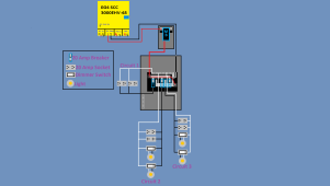
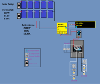
I have en EG4 3000 EHV-48 Solar Inverter/Charger. I have about 2500w worth of panels. At this time I have 1 Lifepower4 51.2V100A Batteries. The system I am building is 100% off grid and never will be on grid. Any further expansion could include more panels, another battery or 2, and more circuits, thats about it.

I am in the stage of my research of now considering the AV output and distribution system. In the manual for this SCC it suggests a 30amp breaker for the AC out, and provides 120V. (At this time i doubt ill add another SCC for split phase 240v, but if I ever did id consider all of that at a further date).

I have a few questions that have come up regarding this seemingly uncommon setup. 120v Load Center wiring direct from a SCC. I have scoured videos for a while but just cant seem to find something that directly represents my situation.

1. Neutral Ground: I have read a few threads regarding this but dont quite understand the full idea with grounding and possible neutral bond in a setup like mine. Hell I dont even understand where I might need to connect to rod that i pound into the ground or if that is on the agenda at all! If anyone is so kind to explain (or provide links) to understand the topology of this concept.

2. LoadCenter: I have a Square D 6 circuit homeline load center (HOM612L100RB). Sense I am only getting 120V out from the SCC, it seems these load centers will only have half of the circuits energized. Id like to make use of the whole load center and have seen the option of running a jumper from the connected Load bus to the other bus. Is this a horrible idea? When ive heard it mentioned, people seem to mince words about it. Is it a better idea to have an external bus bar inbetween my SCC AC output and two "loads" from the bus to each of the separate circuits on the load center?

Here is a video of pretty much the same loadcenter that I have but is being used slightly differently by Will:

Id like to use the same load center powered by my 120v output SCC mentioned above.


Thanks in advanced, I am working on a diagram just in case it helps explain things.
 
Since you are completely off grid you will want to establish a proper earth ground with rod and feed to your load distribution panel. From the load panel will come a ground wire to your AIO chassis ground and my personal preference is to jumper "AC in" ground with chassis ground. Although these units often bond NG when in Inverter operation it seems to help to have the best ground you can establish. I do not know if your AIO bonds NG but if it does the neutral bus in the load center should not be bonded.

Feeding your load center can be accomplished either with a 30a breaker that you use to back feed the panel from one of the slots, or if you use a local disconnect breaker just after your AIO, you then can feed the L1 and L2 (jumper from L1) buses. Neutral from AC out goes to load center neutral bar.
 
Thanks a ton for your reply Matt! That was very helpful. Quick followup question:

If my AIO manual suggests a 30amp breaker on the AC out, I assume that should be stuck to pretty accurately? The reason I ask is because I found that I have this: https://www.homedepot.com/p/Square-...e-AC-Disconnect-QO200TRCP-QO200TRCP/202353314

Its 60 got a 60 amp breaker in it, should I stick with the same housing and buy a 30 amp breaker or is the 60Amp okay sense its purpose is a disconnect switch and not over current protection? (or do you have any better suggestions in general?

I plan to have this as my "main breaker" rather than taking up space in the load center.

Thanks a ton again!
 
See if you can get a 30a breaker to fit in place of the 60a. I suspect it has a means to make the breaker fixed in the panel that code requires for a service breaker. Since it is 240vAC you could jumper incoming L1 and L2 (from the AIO) for now with two hot wires going to your 6 slot distribution panel and if you eventually went up to 240vAC it would allow you to do so with a quick jumper removal and wire.
 
I don't think breaker sized as recommended or oversized will make any difference if not fed from grid (or a large generator).

To fast-trip a 30A breaker's magnetic mechanism in ~ 10 milliseconds would require about 150A
To slow-trip the breaker's thermal mechanism might take 45A for 15 minutes (5.4kW)

So I expect the EG4 3000 EHV-48 to never trip a 30A breaker same as it would never trip a 60A breaker. Either would just serve as a switch.
 
Thank you both very much for the information and suggestions! Ill do some mulling over them and continue mapping out my diagram!
 
It would go like this:

single AIO wiring.jpg

Your background is horrible for working with MSPaint by the way. ?

With this box there is no way to avoid having your N-G bond happen as it appears that the Neutral block is screwed right to the case. No idea how much trouble that's going to cause with the AIO and the breaker box having a N-G bond.
 
It would go like this:

View attachment 161878

Your background is horrible for working with MSPaint by the way. ?

With this box there is no way to avoid having your N-G bond happen as it appears that the Neutral block is screwed right to the case. No idea how much trouble that's going to cause with the AIO and the breaker box having a N-G bond.
Looks good Rednecktek.

If it was me I would establish a neutral wire that just passes by that grounding lug running between AIO and load panel. Use the lug in the disconnect box for grounding only. it could be the spot for house ground and wires running from it to the distribution panel and also the AIO.
 
Very cool thanks a ton again both of you! Will do some diagram work based on yaalls suggestions!

Would yaall by chance be able to explain (or have a good resource) for how that breaker (being 240v) is related to the voltage, vs the 30amp breaker i linked saying its 120/240. Keeping in mind my AIO is 120v AC out and I for the time being only have plans for 120V

Thanks again
 
Most 120/240V breakers are only good for 120V per pole.
From Square D, some breaker models are rated for 277V, and the 3-pole models I think all are. Probably only some of QO series, not Homeline.
Read vendor specs for exact model to be sure.
 
Last edited:
To make sure I understand it right, using the breaker in the picture above as an example (60 amp double pole 240V), if I have 120V comming out of my AIO then do I need to use a jumper as drawn in the picture? or could i just wire one side of it?
 
Each half of the breaker feeds 120v to each of the screw terminals. If you were to only wire the right half you could only get power out of the right screw and vise versa. The jumper just feeds the left side from the wire coming in on the right. Each leg is still 120v so no 240v on there.
 
In your case since you only have a single 120v line, you don't have the option of 240v out of it, but this is how the power flows through the breaker in your box so the yellow 240v means nothing to you, but hopefully this explains how it all works. Since the power goes through either side, that's where that jumper comes in so the left and right sides can both get power flow through them. If you didn't have the jumper and only ran to the RED 120v line, then nothing on the BLUE line would get any power. Does this help make sense?

breaker flow.jpg
 
In your case since you only have a single 120v line, you don't have the option of 240v out of it, but this is how the power flows through the breaker in your box so the yellow 240v means nothing to you, but hopefully this explains how it all works. Since the power goes through either side, that's where that jumper comes in so the left and right sides can both get power flow through them. If you didn't have the jumper and only ran to the RED 120v line, then nothing on the BLUE line would get any power. Does this help make sense?

View attachment 162016
Hey Redneckteck! Thanks for the response and detailed explanation! I do believe it makes very good sense from what you explained/drew. So for my application, I really could just wire up my + from the AIO AC out to the right (red side) nut, then out to the load center from the right side of the breaker to get a 120V circuit through the breaker. The left side would be idol/unused. Should I want to add another 120V load center I could chose to add in the jumper to power the left (blue) side and run that off to another load center if needed (not that I plan to due to the lack of chance that Ill be using that much power or need that many circuits anyways, this is more of a confirmation of understanding). Additionally, should I ever endup with a second AIO i could power both sides to run 240V split phase at that point also.

For my current situation though, based on what I understand ill take the + side of my AIO AC out and power 1 of the 2 sides of this breaker and out from the side of my choosing run that to my power my load center. The neutral from my load center will bypass this pictured box and go straight to my AIO's -. I have attached a partial diagram for better visualization. Hopefully I am gettin all of this right! Sorry in advanced for the crude paint diagram!
 

Attachments

  • Detailed Load Center.png
    Detailed Load Center.png
    170.5 KB · Views: 15
Yup! Your main breaker would have to be a 40a breaker to support all the AIO can send it but that would be perfectly fine. Something to note is that if ANY circuit has a light fixture on it, it's limited to 15a so most of those breakers in the load center need to be adjusted accordingly.

If/When you step it up to 240v split phase you can absolutely use that main breaker's other terminal and just pull the jumper out of the load center. Do yourself a favor when you wire this all up and go ahead and run that 2nd wire while you're pulling everything else, you can just tape up the end and leave it hanging out in there for the future.

When I wired in all the electrical to my pump house, I made it a point to put all my outlets on 20a breakers and my lights on different 15a breakers. Nothing like trying to work on an outlet and not being able to turn on the light to see what you're doing, or to replace the light fixture and not be able to plug in a lamp. :cautious:
 
Last edited:
Ooh very interesting insights! Thanks so much for your assistance and in depth guidance! Ill be sure to keep these things in mind!
 
Thanks so much for everyones input and assistance! I feel like things are starting to come together in my head a bit better!

I have crudely drawn a full diagram of the system I expect to deploy. Any critiques on missing components, better practices, or whatnot would be very much appreciated.


Thanks again very much everyone!
 

Attachments

  • Full Detailed Diagram.png
    Full Detailed Diagram.png
    177.5 KB · Views: 15
Hey Redneckteck! Thanks for the response and detailed explanation! I do believe it makes very good sense from what you explained/drew. So for my application, I really could just wire up my + from the AIO AC out to the right (red side) nut, then out to the load center from the right side of the breaker to get a 120V circuit through the breaker. The left side would be idol/unused. Should I want to add another 120V load center I could chose to add in the jumper to power the left (blue) side and run that off to another load center if needed (not that I plan to due to the lack of chance that Ill be using that much power or need that many circuits anyways, this is more of a confirmation of understanding). Additionally, should I ever endup with a second AIO i could power both sides to run 240V split phase at that point also.

For my current situation though, based on what I understand ill take the + side of my AIO AC out and power 1 of the 2 sides of this breaker and out from the side of my choosing run that to my power my load center. The neutral from my load center will bypass this pictured box and go straight to my AIO's -. I have attached a partial diagram for better visualization. Hopefully I am gettin all of this right! Sorry in advanced for the crude paint diagram!

malfestus

Like that diagram, would like your input on similar, but with TWO EG4 3K's coming MB (calling mine Inverter Combiner Panel) where both 25A 120V outputs come into this panel... then this panel has three outputs... 1) 20A breaker to 20A outlet, 2) 30A breaker to WFDC 30A RV distribution panel/box (existing RV power center); 3) 30A breaker to sub panel. Was just confused about bringing in / combining to single phase 50A 120V 6000W availability.
 
Hello All!

I have finally made it to the point of installation of my system thanks very much to the input and help of many here (very much appreciated).

At this point, I have installed essentially what is in this updated diagram, but have NOT installed the PV array yet.
Note: This is a fully off grid system.

The only thing not shown here is an added chargerverter that uses a portable generator to pump the batteries full. Additionally, none of the branch circuits have been installed (off of the load center).

My current concern that I cannot find a clear answer to for this particular setup is:

Do I need, and if so where, a true ground (like a copper rod drove into the ground). And if so, what is the best location to connect it do?

Thanks again for everyone's help!
 
Do I need, and if so where, a true ground (like a copper rod drove into the ground). And if so, what is the best location to connect it do?
Yes, you'll want a proper ground rod setup and it'll connect to the ground bar in the main panel most likely. This subject always gets a little hairy though because some inverters do the N-G bond internally, some don't, and some do it only when it's running from battery and disconnects it when AC power is put into it.

You'll need to grab a meter and poke the AC outlets when it's powered off and see if you get connectivity between your AC output Neutral and the Ground. If the inverter is doing the N-G bond then the rods in the dirt will connect to the G terminal in the inverter, and the bonding screw in your main panel will be removed. That should make the inverter a single point of N-G bonding.

Just to be safe though, pinging @timselectric is never a bad idea.
 
Thanks for the reply Rednecktek!

Okay, I have taken my meter and poked the Neutral AC out, and the ground screw on the case. I get 0-.2V.

I saw this thread regarding my same inverter and from the looks of it, my inverter has a good N-G bond (is that the correct language?).


IF my inverter is indeed doing the N-G bond then:
1. Ill install a grounding rod near the inverter and connect it to the grounding screw on the inverter.
2. The bonding screw of my load center is removed.
a. Where do i connect the ground for each circuit at this point? Do they still connect to the ground bar in the load center?


Thanks again!
 
Yes, if the inverter is doing the N-G bond then all your circuits would ground to the ground bar in the panel, the neutrals will have a separate bar for them, and each of those would have a separate conductor to the inverter.
 

diy solar

diy solar
Back
Top