Yes and no. Firstly understand that the '24V' is the
output to the battery, the
input is from your PV panels. A 100W panel would typically generate around 22V (open circuit) so three in series would be 66V ... this is oft called the 'system voltage' and must be supported by your charge controller (
most offer up to at least 75V). Paralleling these two series connected strings would double the available current whilst maintaining the same system voltage. A 300W series connected panel string would generate around 6A (at 66V) so doubling up would be 12A (at 66V).
So, yes, you can connect your panels in this way, but no, they would not make 24V. Clear as mud?
Not sure what you mean.
Imho, you don't need to fuse PV lines so long as you have spec'ed the PV cable correctly, though adding an isolation switch is a good idea.
After making sure that the cable from controller to battery and battery to load is spec'ed correctly*, you should fuse the controller to battery line (
at just above max current your controller is specified for) and from battery to load (
at just above max current for expected loads). Remember fuses are just there to protect the wiring from short circuit overloads; the devices they connect to have their own protection. It is also a good idea to have a battery isolation switch.
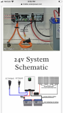
Will's website has a load of good blueprints for typical installations:
https://www.mobile-solarpower.com/
*To spec wire:
(1) Ensure the cable is capable of supporting the maximum expected current
(2) Ensure the cable run (i.e. there and back) does not drop more 3% of the supplied voltage across it
(3) Ensure the cable (and connector) specs are suitable for the intended use e.g. use dedicated PV cable for PV runs, automotive cable for internal runs, tinned copper lugs etc.
Other installation considerations:
- Keep the PV cables long to ensure controller and battery cables are short as possible in order to reduce resistive losses.
- Use a proper crimp tool and good quality terminals for battery and load terminals - you don't want these arcing or corroding.
- Over-spec'ing cable just adds weight and cost to your project without any appreciable benefit.
- It's a general rule of thumb to spec your battery bank to provision 3 days expected daily usage and your PV array to replenish daily use per day. For example, Daily Usage = 1,200Wh, spec 300AH battery bank (1,200Wh x 3 days = 3,600Wh / 12V = 300AH) with 240W total panels (240W x 5 hours sun = 1,200Wh per day). Remember though that depending on your latitude from the equator, solar energy reduces. I live in England at 55o latitude, my rule of thumb is 80% efficiency in Summer dropping to 20% efficiency in Winter.
I hope this helps,
Regards,
David.


")