diy solar

diy solar

3 strings parallel - different tilt

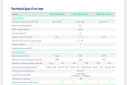
It seems that the 400v battery hybrids are cheaper than the 48V ones by a healthy margin.

The biggest hurdle is finding a distributor who actually has it.

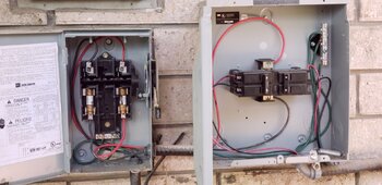
My existing 2 inverters' output goes into the panel below which seems to have the purpose of joining the 2 inverters to one line, and from there to the blade switch on the left. And from there into the main panel feeding into the grid.

I think I can leave everything as is and just put the new single inverters output into one of these 2 breakers. May need to upgrade from 15A to 25A though.

Am I right?
20240713_125114.jpg
 
The biggest hurdle is finding a distributor who actually has it.
I saw the Growatt on Renvu , for drop ship. But $1299 list price, not the $400 discount of signature solar

Yes you can put in a bigger breaker, should be cheap.

6000/240*1.25 = 31.25 which rounds up to 35A breaker. You will need to upgrade the AC wiring to #8. Is the knife disconnect wiring and fuse already big enough? Should be big enough already for the 3300 watt original.
 
So one thing a few folks in the forum have done (on my suggestion) is use high power Hoymiles microinverters. (The risk with your setup is , grounded panels, and no EGC which may cause the inverters to fail safety check). The amusing thing about this is that you can take 2-4 old panels and plug them into a single port meant for one modern panel.

One of the 2000W ones can probably handle one of your 20 panel sub arrays. They have four ports each, you can do 2S2P into each port (you can even do 3P and stay under the ISC). That is 16 panels without any clipping. It will cost a little more than the optimizers. They are out of stock in the US right now but should be around again shortly.

If you have 4x #12 to the array you can put two of these on a single circuit, and then use 1 of the remaining for an EGC (not code compliant due to colors but I doubt anyone will bust you). These do have transformer isolation but are I believe intended for ungrounded panels.

IMG_5864.jpeg
IMG_5863.jpeg
 
6000/240*1.25 = 31.25 which rounds up to 35A breaker. You will need to upgrade the AC wiring to #8. Is the knife disconnect wiring and fuse already big enough? Should be big enough already for the 3300 watt original.

the "solar breaker" in the main panel is a double-pole 30A breaker and the wire looks like AWG 10. Each inverter was on a 15A breaker in the outdoors panel shown above.
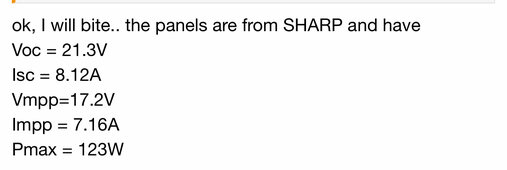
The old Sunnyboys were perhaps 3kW each, or even just 2.5kW.. the original solar array has a max output of 40*123W = 4920W
The panels were originally all hooked up with AWG 12. When I relocated the array in 2020, due to the now longer run, I increased it to 10 AWG.

Based on inverter nominal rating, the calculation is 6000/240*125 = 31.25
Based on max pv output, it would be 5000/240*1.25 = 26.04A

Wouldn't a 30A breaker be enough? Keep in mind, I only measured ~95W per panel at noon on a sunny day in July.
The total output on the DC side is likely 3.8kW (after I replace the diode LOL) which means it's going to be 3700W on the AC side.

The real max current is then 3700W / 240 = 15.5A and after *1.25 .. a 20A breaker would actually suffice.

I'm just concerned if I change the AC wire from the inverter to the blade switch, then I also need to upgrade the solar breaker in the main panel from 30A to 35A. I really don't want to change these, in case someone from the PoCo ever looks at it. I can show them that I have the original input breaker (30A) and the original panels from 2004.

I was looking to rather buy a 6kW inverter instead of a 5kW model to keep the load as a % of max capability a bit lower.
 
and no EGC which may cause the inverters to fail safety check

are you saying the lack of EGC would cause the Hoymiles inverter to fail the safety check, or the GroWatt 6kW? I noticed that the GroWatt does have several safety checks - although most of them seem to pertain to the AC side- I was wondering already if my configuration will allow the GroWatt to actually start up:
  • Type III AC surge protection
  • AC short circuit protection
  • Ground fault & grid monitoring
  • AFCI protection (Arc Fault Circuit Interrupter)
  • Rapid shutdown capable, RFCI protection (Rapid Shutdown Arc Fault Circuit Interrupter)
  • Anti-islanding protection
  • Residual-current monitoring

If you have 4x #12 to the array you can put two of these on a single circuit, and then use 1 of the remaining for an EGC

Even better, I have 4x #10 to the array, and IIRC, in black, black, white, green.
However, if I use two on a single circuit and one for EGC, how do I hook up the 2nd circuit?
 
Last edited:
Wouldn't a 30A breaker be enough?
Probably would be fine (though not code compliant) as long as there are no false trips. Actually a lot of people have breakers that were mistakenly off by 5A.

Also, the wire being protected is pretty short and well behaved.

Thing to watch out for would be nuisance trips.

Based on max pv output, it would be 5000/240*1.25 = 26.04A
There is some potential for extra production on some days, which adds to this, and factoring in inverter efficiency of maybe 96%, which subtracts from this.

I was looking to rather buy a 6kW inverter instead of a 5kW model to keep the load as a % of max capability a bit lower.
OK. You could also get some safety factor/address breaker trips if the inverter supports output power cap.

Grid tie inverters run at 100% a lot more than off grid inverters and hybrids. In the latter case the battery charging and conversion circuits take the brunt of it
 
are you saying the lack of EGC would cause the Hoymiles inverter to fail the safety check, or the GroWatt 6kW?
More likely on the Hoymiles because the EGC is on its AC output and microinverters I believe do ground quality checks while they are starting up. The Growatt 6K probably will be fine. The SolarEdge optimizers will be fine too because they have no connection to EGC

I was wondering already if my configuration will allow the GroWatt to actually start up:
You might check in the manual or with owners on what can be disabled. I know a lot let you disable AFCI or change sensitivity (though, this might be a bad idea to disable since DC arc faults are probably the 2nd big fire risk after batteries).

Even better, I have 4x #10 to the array, and IIRC, in black, black, white, green.
However, if I use two on a single circuit and one for EGC, how do I hook up the 2nd circuit?
Your white and green are not valid colors for current setup 🤣. Oh well.

You put the AC output of both of the two multiport microinverters (each with either 16 or 20 panels plugged into them) on the black, black, and green.

Each #10 set can be assigned to a 30A AC branch circuit, and this is the AC trunk bus for the microinverter output. You can put any combination of microinverters adding up to 5.7kW. The two I linked are 2kW each, so another 1.6kW can be added on top of that. They actually make 1.6, 1.8, and 2.0 kW output capacity microinverters, along with providing API access to throttle the individual microinverters if you don’t want them to output the full amount.

There’s some cool stuff you can do with this config. Like (code violating) put some AC loads on this circuit. Or extend the trunk to accept a set of random spec panels on another roof plane

I have 20kW of this brand’s previous gen microinverters on my roof, for coming up on 2 years.

I’m sure Hedges is not going to like adding MLPEs 🤣. Mostly I thought of these because the grid tie inverters were starting to look kind of expensive and annoying to buy.
 

diy solar

diy solar
Back
Top