diy solar

diy solar

4 x Pylontech US3000C, MCB/amps and Solis inverter

jploh

New Member
Joined
Jul 17, 2023
Messages
6
Location
Philippines
My set up is a Solis hybrid inverter with 4 units of US3000C in parallel. In between the master battery and the inverter is a 125A MCB (Suntree SCB-125DC).

Recently, the MCB has been tripping and heats up from 3 to 3.5kW or higher. A portion of the cable close to the MCB is hot while the rest of the cables are in room temperature. The installer came today to inspect the MCB and it's suspected that one of the cables may have been tugged a bit. We still suspect that the MCB is underrated based on another thread here.

It would be 72A at 3.5kW 48V if the calculator I used is correct. Haven't been able to see on the inverter the actual charging current in amps - apart from the charge/discharge limit set to 148A.

I have a 5th unit to connect to the battery group, and possibly a 6th, so I'm wondering if the charging current could be lowered by putting the batteries in multi-group mode. If not, I guess there's no choice but to go with a higher capacity MCB? My inverter also says it's capped at 100A charging current. I tried lowering this but it may have a bug in the firmware as the change doesn't stick. It's also possible that the Pylontech is overriding this setting as described above.

We're also evaluating having a bus bar or terminal block and have multiple MCBs and divide the batteries.

Any advice would be appreciated.
 
The limiting factor would be the inverter. However many batteries you have the max current will be limited by the Solis. Assuming you have the RHI 5 or 6kWh, that is 100A, as you noted.

Sounds like an issue with the MCB itself or the connection to it. What size dc cables do you have?

If you can't see the current charge rate in amps on the info pages (as I mentioned on your other thread), then you should be able to see the charge going to or from the batteries on the main screen of the RHI Solis - this will be in kW, rather than amps. The voltage of the batteries should be visible in the info pages, otherwise, just divide the Watts by the nominal 48V of the 15 cell pylontechs to get the current in Amps.
 
The limiting factor would be the inverter. However many batteries you have the max current will be limited by the Solis. Assuming you have the RHI 5 or 6kWh, that is 100A, as you noted.
In addition to that, the inverter will get too hot if charging at 100A for any length of time and will throttle back to 85A. If you set it to 85A it won't need to throttle back any further.
 
In addition to that, the inverter will get too hot if charging at 100A for any length of time and will throttle back to 85A. If you set it to 85A it won't need to throttle back any further.
Interesting... I wonder how on earth I missed that info in the Solis sales brochures / website :( ? Maybe they put it in a small font like Amazon do sign you up for Prime subscriptions :ROFLMAO:

Guess you could use a few of the wasted amps to add a better fan to the Solis like @peufeu did?
 
In addition to that, the inverter will get too hot if charging at 100A for any length of time and will throttle back to 85A. If you set it to 85A it won't need to throttle back any further.
Here's the post:


I started with a stone wall. It's impossible to drill accurately in stone, so I mounted an OSB board on it, hung with screws and anchors. Then I put a drywall sheet on it for fireproofing. I don't like mounting electrical stuff on wood. I mounted the inverter, panel, breakers, etc, much easier to screw all this into OSB.

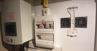
So when the Solis overheated ("fanless" ftw) I created some space between the wall and the OSB sheet by inserting some 1" wood battens between the OSB sheet and the wall, cut some holes, and put Arctic P12 PC fans. You can see them on the right, on both sides of the mounting bracket for the second Solis, which is not mounted yet because it's waiting for an underground cable to the shed's panel (trench digging tomorrow morning).

1689804576530.png

Since I have a Pi logging solis data, it triggers a Tasmota smart plug based on inverter temperature, and that turns on a 12V power supply for the fans.

Since then, no trouble charging at 100A, it's just getting a bit warm instead of scorching hot.

I picked Arctic P12 because it's cheap, not too noisy, and has good pressure. In fact I bought the high pressure fans because I intended to mount them on top of the inverter blowing down on the heat sinks. I tried that but it required a lot of tape on the edges to keep the airflow inside the heatsink and not blowing out the sides. Mounting them behind the inverter turns out to work better (lower measured temperature) and they're out of the way, if they break down the airflow should be identical to "no fans" instead of having a dead fan blocking the airflow. And they blow air into the heat sink instead of across, which seems to work better.

120mm fans are just the right size for this style of mounting. It would probably work even better with F12 fans which are optimized for flow instead of pressure, but well, it's done. I'll probably use the PWM feature someday.

This "6kW" inverter has 9.6kW of panels on it, with enough sun it has no trouble charging the battery at 4.9kW while outputting 3kW on the grid.

The 48V DC-DC is in the lower right corner and it's the part that produces most heat, so if you use only one fan, you should put it on the left side. But at 6€ each why bother.

It's quite hilarious this "fanless" model has two fans inside. It's hard not to notice them given how much noise they make.
 
Last edited:
Here's the post:
Nice setup. I don't have that issue with my 3Kw inverter, but I was thinking about putting a couple of small fans under the inverter to blow a bit of air at it if it does get hot. I have a Pi logging data too, and local temperature. It has access to the Modbus, so I could have it switch on the fans if the inverter gets too warm.

I like your idea of mounting the fans through the backboard. I'll consider that if I ever get a bigger inverter.
 
Yes, I wanted to put the fans on the bottom at first but it's a bit cramped with all the connectors, 120mm fans will not fit, so the next size down is 92mm which has significantly lower airflow. Also putting the fans at the end of the heatsink means all the airflow escapes between the heatsink and the backboard, and not much between the fins. It's possible to add a plate at the back to channel the air into the heatsink but then it wouldn't work at all without the fan. In the end it works better blowing into the heatsink from behind.

Arctic P12
Airflow: 56.3 cfm (95.7 m³/h)
Static Pressure: 2.20 mmH2O
Power: 1.92W

Arctic F12:
Airflow: 53 cfm (90.1 m³/h)
Static Pressure: 1 mmH2O
Power: 1.44W

So it's not necessary to use a high power noisy leafblower

One reason I don't like the wifi smartplugs : if my internet connection goes down, the ISP's fiber box also goes down and turns off wifi.

I'm going to get a 48V to 12V isolated DC-DC converter from Meanwell (plus a 12V to 5V buck) and power the Pi and fans from the 48V battery. That will give the Pi an UPS and remove the wifi smartplug.
 
Interesting set up with the fans! It is hotter where I am and the Solis model that I have has a fan kicks off when at higher currents. Will start with getting telemetry through Solarman and HomeAssistant. Still waiting for my installer to replace the MCB. On another note, I've asked him to look for a non-polarity DC MCB as a replacement - this is better for isolation and protection on the battery side with Pylontech, right?
 
The installer got back to me with a DC polarized MCB and the original cable returned. Will be giving it another try with 125A. Confirming that the cable is 4 AWG.
 
Back
Top