


You are using an out of date browser. It may not display this or other websites correctly.
You should upgrade or use an alternative browser.
You should upgrade or use an alternative browser.
Active balancer or not?
- Thread starter MullerEnergy-Australia
- Start date


Capt Bill
Sailing Options
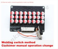
Here's another picture of that switch option on the 8S model. Been thinking of using this on my funky 24vset of 280ah that has some runner/ peakers near the top charge voltages that trigger my BMS. Wonder if setting this kind of Active Balancer to automatically turn on at just the higher charge voltage range (can think of way to automate that), ...Wonder if that would be better for my battery cells than letting the active balancer run 24/7 ???BTW, on Heltec Active Balancers:
View attachment 56600
See that spot where it says "RUN"?
That's actually two separate electrical connections. You can simply remove the blob of solder there and wire in a physical switch instead. This will allow you to control the active balancer manually.
Just thought I'd mention this, to soothe any worries that it might go haywire....
As always, ensure that any balancer used is properly configured for the battery chemistry you're using and for the specific safety range you desire.
Attachments
Horsefly
Solar Wizard
Short answer is YES, it would be better to balance nearer the top of the charge curve than throughout the charge curve. The key will be how you implement what you are describing. A relay that is controlled based on the battery pack voltage, with the relay switched terminals wired to connect / disconnect across the RUN terminals would do it.Here's another picture of that switch option on the 8S model. Been thinking of using this on my funky 24vset of 280ah that has some runner/ peakers near the top charge voltages that trigger my BMS. Wonder if setting this kind of Active Balancer to automatically turn on at just the higher charge voltage range (can think of way to automate that), ...Wonder if that would be better for my battery cells than letting the active balancer run 24/7 ???
Depending on your usage, it may be OK to simply have the balancer run all the time. If your battery normally doesn't discharge into the lower knee of the cells voltage curves, the balancer will not really be causing a problem. However, if you do routinely get into the lower knee, the balancer will be effectively undoing whatever top balance you may have done, balancing on the bottom and then trying to re-balance again on top in each cycle.
For the packs that I've built with the JBD / Overkill BMS, I simply wired a SPST switch across the RUN terminals of the Heltec active balancer. Normally I just leave it off, but if I observe the cells getting (and staying) out of balance when in the upper part of the charge curve I will turn it on.
One word of warning: I had one of the 8S boards just like the one your pictured go bad. It was running full time on a 230Ah 24V pack that I was testing in the garage, and something happened to the board. It got very hot, and it drove one of the cells quite a bit out of balance. My application for this pack is unattended for most of the time, so I replaced the Heltec board with a new one and put in the switch and will keep the board off except when I know balancing is needed.
More recently I've purchased a single JK BMS with 2 Amp active balancer. Set to only balance above a set cell voltage (I have mine set to 3.38V) you can watch it balance on the Bluetooth app. So far I think it does a much better job than the using one of the standalone active balancers, but the way you have described would be an acceptable way to make it work.
curiouscarbon
Science Penguin
- Joined
- Jun 29, 2020
- Messages
- 3,024
it's very likely that only a very small electrical current goes through the "RUN" switch pins, so a very small relay should suffice.Do we know how big of a relay we would need to use it as a switch for the Heltec balancer? Ideally I'd only want to engage the balancer in e.g. Python via Raspberry Pi when needed.


Adafruit Non-Latching Mini Relay FeatherWing
A Feather board without ambition is a Feather board without FeatherWings! This is the Non-Latching Mini Relay FeatherWing. It gives you power to control, and control over power. ...
 www.adafruit.com
i have a few of these small Normally Open relays around, and for automated control would connect the relay control to an arduino microcontroller or something.
one pin of RUN goes to COM on relay
other pin of RUN goes to NO on relay
then a logic pin to the Signal input of the relay will close the relay and connect the RUN pins and enable the active balancer.
might even connect a manual switch in series for manual lockout shutoff sort of thing.
one curiosity i have is if the RUN switch will stop a malfunctioning balancer from "runaway" as @Horsefly described experiencing
Horsefly
Solar Wizard
I have some similar relay boards I bought a few years ago. At first I thought yours was better for this application because mine include an optoisolator and so requires a Vcc source. But then I noticed that yours requires a 3.3V Vdd as well, or at least it looks like it does. Have you tried to uses these outside of the ESP8266 environment?it's very likely that only a very small electrical current goes through the "RUN" switch pins, so a very small relay should suffice.
View attachment 93988
Adafruit Non-Latching Mini Relay FeatherWing
A Feather board without ambition is a Feather board without FeatherWings! This is the Non-Latching Mini Relay FeatherWing. It gives you power to control, and control over power. ...
i have a few of these small Normally Open relays around, and for automated control would connect the relay control to an arduino microcontroller or something.
one pin of RUN goes to COM on relay
other pin of RUN goes to NO on relay
then a logic pin to the Signal input of the relay will close the relay and connect the RUN pins and enable the active balancer.
might even connect a manual switch in series for manual lockout shutoff sort of thing.
one curiosity i have is if the RUN switch will stop a malfunctioning balancer from "runaway" as @Horsefly described experiencing
Capt Bill
Sailing Options
Thanks for Heads Up re potential danger of unmonitored use.Short answer is YES, it would be better to balance nearer the top of the charge curve than throughout the charge curve. The key will be how you implement what you are describing. A relay that is controlled based on the battery pack voltage, with the relay switched terminals wired to connect / disconnect across the RUN terminals would do it.
Depending on your usage, it may be OK to simply have the balancer run all the time. If your battery normally doesn't discharge into the lower knee of the cells voltage curves, the balancer will not really be causing a problem. However, if you do routinely get into the lower knee, the balancer will be effectively undoing whatever top balance you may have done, balancing on the bottom and then trying to re-balance again on top in each cycle.
For the packs that I've built with the JBD / Overkill BMS, I simply wired a SPST switch across the RUN terminals of the Heltec active balancer. Normally I just leave it off, but if I observe the cells getting (and staying) out of balance when in the upper part of the charge curve I will turn it on.
One word of warning: I had one of the 8S boards just like the one your pictured go bad. It was running full time on a 230Ah 24V pack that I was testing in the garage, and something happened to the board. It got very hot, and it drove one of the cells quite a bit out of balance. My application for this pack is unattended for most of the time, so I replaced the Heltec board with a new one and put in the switch and will keep the board off except when I know balancing is needed.
More recently I've purchased a single JK BMS with 2 Amp active balancer. Set to only balance above a set cell voltage (I have mine set to 3.38V) you can watch it balance on the Bluetooth app. So far I think it does a much better job than the using one of the standalone active balancers, but the way you have described would be an acceptable way to make it work.
Here is the Voltage Monitor with Relay Coil voltage options of 12v 24v or 48vdc : says"
The voltage monitoring relay could achieve real-time monitoring of dc overvoltage and undervoltage ...
It settings will trigger a shift a its' built-in 6A 250VAC DPDT relay. The bottom dial is a delay dial for 0.1 to 15 seconds.
I am testing a couple of these: It appears the Top Dial is for catching high volt limit as voltage rises to trigger a relay shift; and the middle dial catches low volt limit as voltage drops, to reset relay. I am going to use this for relay control of some AC circuits; to limit some heating water tasks to times when my battery voltage is near top of charge. I can see using it same way on the Heltec 5A active balancer's switch option. ... I think automating the active balancer to work only at higher charge voltage may make if safer, and possibly more effective. ???
Horsefly
Solar Wizard
That device certainly looks like it would do the trick. I'd feel better if they listed how much power it consumed both with the relay ON and with it OFF, but maybe it is OK.Thanks for Heads Up re potential danger of unmonitored use.
Here is the Voltage Monitor with Relay Coil voltage options of 12v 24v or 48vdc : says"
The voltage monitoring relay could achieve real-time monitoring of dc overvoltage and undervoltage ...
It settings will trigger a shift a its' built-in 6A 250VAC DPDT relay. The bottom dial is a delay dial for 0.1 to 15 seconds.
I am testing a couple of these: It appears the Top Dial is for catching high volt limit as voltage rises to trigger a relay shift; and the middle dial catches low volt limit as voltage drops, to reset relay. I am going to use this for relay control of some AC circuits; to limit some heating water tasks to times when my battery voltage is near top of charge. I can see using it same way on the Heltec 5A active balancer's switch option. ... I think automating the active balancer to work only at higher charge voltage may make if safer, and possibly more effective. ???
It would be more expensive, but I think I would prefer using a Victron Smart Battery Protect and a small regular relay. This model of the Battery Protect costs about $60, and lets you set the exact voltage to turn-off using the Victron Connect Bluetooth app: https://www.amazon.com/Victron-Smart-BatteryProtect-Bluetooth-BPR065022000/dp/B07MXG5XZ4 I just tend to like doing it that way rather than tweaking a dial with a small screwdriver. It also consumes very little power when it is off. That is only logical, since the device is normally intended to preserve your battery if the voltage gets low by cutting off loads. In this case the battery protect would only power the NO relay to close the connection of the balancer "Run" pads. So my solution would be more expensive and would require two devices (the relay and the Victron Smart BP), but I'm pretty certain it would draw less current
Bossrox
Solar tinkerer
Those heltecs work pretty good but they claim up to 5 amp balance which is bunk. About 1 amp is the best they'll do. I tested mine to find that out 'cuz I have a really out of wack pack that takes 5 of those boards stacked to keep it in line.
Capt Bill
Sailing Options
I like learning from these threads, and this forum's search engine. ... For that $25 Voltage Monitoring Relay on Amazon (I posted above) .. this is from the QsAns: What is draw from the 12v (24v or 48v) supply? A: Slightly more than enough current to operate a simple status LED built-in to this device, as well as a the tiny internal relay coil current for this device's controlling contacts: a small number of milliamps is the current draw from this device for its operation. ... & another A: .. I measured the operating current for the device and it is simply insignificant, ... My Capt Bill Thoughts: The little screw driver is a little challenging, but fine tuning it to get want seems very possible. I will just have see about its longevity. I seem to be stocking extras in my supplies for experimenting like this. I like learning from my research, and then via my hand on the details :+) Thanks for comparing notes, and that Victron option.That device certainly looks like it would do the trick. I'd feel better if they listed how much power it consumed both with the relay ON and with it OFF, but maybe it is OK.
It would be more expensive, but I think I would prefer using a Victron Smart Battery Protect and a small regular relay. This model of the Battery Protect costs about $60, and lets you set the exact voltage to turn-off using the Victron Connect Bluetooth app: https://www.amazon.com/Victron-Smart-BatteryProtect-Bluetooth-BPR065022000/dp/B07MXG5XZ4 I just tend to like doing it that way rather than tweaking a dial with a small screwdriver. It also consumes very little power when it is off. That is only logical, since the device is normally intended to preserve your battery if the voltage gets low by cutting off loads. In this case the battery protect would only power the NO relay to close the connection of the balancer "Run" pads. So my solution would be more expensive and would require two devices (the relay and the Victron Smart BP), but I'm pretty certain it would draw less current
Last edited:
I think I read 1 amp per 100 mV differential. So need to be off half a volt to get the 5 amps.Those heltecs work pretty good but they claim up to 5 amp balance which is bunk. About 1 amp is the best they'll do. I tested mine to find that out 'cuz I have a really out of wack pack that takes 5 of those boards stacked to keep it in line.
Capt Bill
Sailing Options
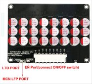
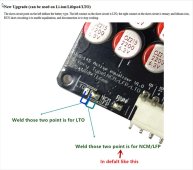
I think the balancer is set to start up at 2.0 volts, sleep at 1.9v or less, and run at 2.0v -4.2 volts (spec on second line from top of data info) ... so for LifePO4 ... run 24/7 unless you install an off and on switch. ... Here's a couple of pictures of balancer board that show how solder on various jumper terminals might change the operating specs., or not ??? Looking at those specs has me thinking it may be important to un-solder the run terminals to install an on and off switch. I will definitely test this Balancer out with an off and on switch while doubting I would be letting it run 24/7. ... I think automating the run switch to turn the balancer board ON @ > 3.4v would likely make it safer, plus possibly very useful on one of my below par 24v 280Ah Eve Battery Banks to dampen the peaker/runner cells that jump up in voltage ahead of the other cells near full charge. I Will Be Testing it out to find out more. My Two more cents :+)In my looking into active balancers, I am seeing that you really need to look at specs before choosing. I have several weeks before my cells arrive, and I am now choosing to not active balance, but depending on what I know a few weeks from now, I may purchase one.
Here are today's issues that's causing me not to active balance:
===================================
Do active balancers only work with low cell voltage? Or is this dependent on the manufacturer.
I am looking at this off alibaba for a Heltec Capacitance Balancer 6S 7S 8S 5A :
View attachment 56611
Balance starting voltage: 2.0V-2.8V ... With my EVE 280 cells having a charge voltage of up to 3.65, and a discharge cutoff voltage of 2.5 volts, this tells me an active balancer only works when the state of charge is really low. Perhaps this is bottom balancing.
Attachments
Last edited:
Horsefly
Solar Wizard
Actually, I think they are completely inaccurate, but with some major caveats. The 5A that you may see is if there is some huge delta between the lowest and highest cell. Since it isn't really "smart" it is just taking what excess energy it sees and moves it from high to low. I agree it is deceptive the way they describe it though.Those heltecs work pretty good but they claim up to 5 amp balance which is bunk. About 1 amp is the best they'll do. I tested mine to find that out 'cuz I have a really out of wack pack that takes 5 of those boards stacked to keep it in line.
Capt Bill
Sailing Options
While I am attracted to that QNBBM 8S active balancer as my backup option to the less expensive Heltec Balancer;
... Wondering if anyone ever experimented with one of these $10 Active Balancers ???

 www.aliexpress.com
Technical Parameters:
www.aliexpress.com
Technical Parameters:
Operating voltage range: 2.0V-4.5V, Li-ion/Lipo/Lifepo4/18650 lithium battery universal.
balance current: Adjacent voltage difference is 0.1V or more (current is about 0.5-0.7A);
Adjacent voltage difference is above 0.2V (maximum balance current is 1.2A);
... or this JK Smart Balance for $69 (Looks Interesting to me:
 www.aliexpress.com
★ Support all pool types such as : Li-ion, Lipo, Lifepo4, LTO, ... s
★ The balance current is set independently in the range of 0.1~1A/2A/5A/10A, independent of the cell voltage difference.
★ ...
★ Support Bluetooth communication, equipped with mobile APP, real-time view of battery status..
Not Sure what this means. if this is deal killer? ★ Power supply range: 40V~ 100V.
... Wondering if anyone ever experimented with one of these $10 Active Balancers ???
9.59US $ 12% OFF|1.2a Active Equalizer Balancer 4s 8s Li-ion Lifepo4 Lipo 18650 Lithium Battery Energy Transfer Active Balance Board Bms 12v 24v - Battery Accessories & Charger Accessories - AliExpress
Smarter Shopping, Better Living! Aliexpress.com
Operating voltage range: 2.0V-4.5V, Li-ion/Lipo/Lifepo4/18650 lithium battery universal.
balance current: Adjacent voltage difference is 0.1V or more (current is about 0.5-0.7A);
Adjacent voltage difference is above 0.2V (maximum balance current is 1.2A);
... or this JK Smart Balance for $69 (Looks Interesting to me:
65.32US $ 29% OFF|Jk Smart Balancer 24v 36v 48v 60v 8s 10s 12s 13s 14s 16s 1a Active Balancer Equalizer Bluetooth Li-ion Lifepo4 Lto Battery Pack - Battery Accessories & Charger Accessories - AliExpress
Smarter Shopping, Better Living! Aliexpress.com
★ Support all pool types such as : Li-ion, Lipo, Lifepo4, LTO, ... s
★ The balance current is set independently in the range of 0.1~1A/2A/5A/10A, independent of the cell voltage difference.
★ ...
★ Support Bluetooth communication, equipped with mobile APP, real-time view of battery status..
Not Sure what this means. if this is deal killer? ★ Power supply range: 40V~ 100V.
Last edited:
Horsefly
Solar Wizard
I had tried one of these inductor-based active balancers, just because they were so cheap. I tried to run it through the same tests I did with the Heltec capacitor-based balancer, purposely taking one cell >100mV out of balance with the others. Unlike the capacitor-based unit, I could not see it do anything after several hours. I suppose it could mean that I just got a defective unit, but it was enough data for me, so I've avoided them since then.While I am attracted to that QNBBM 8S active balancer as my backup option to the less expensive Heltec Balancer;
... Wondering if anyone ever experimented with one of these $10 Active Balancers ???
I've heard good things about this balancer, but yeah it does require a power supply unless you are using it on a 16S pack. That isn't hard (just add a boost converter), but it is one strike against it.... or this JK Smart Balance for $69 (Looks Interesting to me:
★ Support all pool types such as : Li-ion, Lipo, Lifepo4, LTO, ... s65.32US $ 29% OFF|Jk Smart Balancer 24v 36v 48v 60v 8s 10s 12s 13s 14s 16s 1a Active Balancer Equalizer Bluetooth Li-ion Lifepo4 Lto Battery Pack - Battery Accessories & Charger Accessories - AliExpress
Smarter Shopping, Better Living! Aliexpress.com
★ The balance current is set independently in the range of 0.1~1A/2A/5A/10A, independent of the cell voltage difference.
★ ...
★ Support Bluetooth communication, equipped with mobile APP, real-time view of battery status..
Not Sure what this means. if this is deal killer? ★ Power supply range: 40V~ 100V.
This is somewhat older unit now. If you are thinking about the JK active balancer, why not just get a JK BMS that has the active balancer built in?
Last edited:
Capt Bill
Sailing Options
Horsefly
Solar Wizard
Or - like I suggested and Andy showed in the video - use the JK BMS that does active balancing only at the top of the charge.this: Testing 3 battery banks with and without active balancer ... is great info. for this thread. ... has convinced me using active balancer at only the higher charge voltages ...like >3.4 v ... Is a Very Good Idea.
Capt Bill
Sailing Options
That JK BMS with an active balancer looks really good. I would like the 4-8S version to be in stock (might be soon) ... and want to understand the LCD screen options, and wiring between BMS and LCD. Also just noticed the newer Chargery BM16P version that says: Balance current:1.2A per cell continuously. wonder if we have any reports or reviews on that one yet ??? https://www.aliexpress.com/item/32977318118.html?spm=a2g0o.detail.1000023.9.ee4440c75Z9ok1If you are thinking about the JK active balancer, why not just get a JK BMS that has the active balancer built in?
Capt Bill
Sailing Options
So I am hearing: JK BMS that does active balancing only at the top of the charge (and want to confirm info./think it is adjustable/ & want to understand the specific options), ...while the newer Chargery BMS16P description page says "Balance current: 1.2A per cell continuously". I think the Chargery BM P versions may be adjustable like the passive balancing act of the Chargery BMS8T and BMS18T version (because I think they use the same firmware updates). I am asking Jason @ Chargery via resent email, ... to clarify the Chargery P balance options. ... I wonder what real time test result will reveal.??? ???Or - like I suggested and Andy showed in the video - use the JK BMS that does active balancing only at the top of the charge.
Last edited:
Similar threads
- Replies
- 5
- Views
- 527
- Replies
- 6
- Views
- 2K
- Replies
- 13
- Views
- 1K
- Replies
- 87
- Views
- 7K