contractor_chris
New Member
awesome thanks. i just realized some how this thread is in a forsale section. dont have a clue how i managed that haha im shocked ive gotten this many replies having it in the wrong spot 


Basic functionality in terms of operating mode (off, charge only, invert) etc can be achieved using the Bluetooth to ve.bus dongle and victronconnect afaik.
but that is a separate unit then the one i need to purchase to program the unit, right? (so many pieces to buy hah)yes. The VE.BUS smart dongle + Victron connect gives the same function as the control panel.
You only need the USB to ve bus cable if you need to do things like program assistants. For regular everyday configuration you can do it via Bluetooth.but that is a separate unit then the one i need to purchase to program the unit, right? (so many pieces to buy hah)

Yes. The AC output should also have a breaker on it.
You only need the USB to ve bus cable if you need to do things like program assistants. For regular everyday configuration you can do it via Bluetooth.
but that is a separate unit then the one i need to purchase to program the unit, right? (so many pieces to buy hah)
Ah my apologies. So the screens the victronconnect demo mode show for a multiplus must be for when connected via a USB->ve.bus adaptor, the usb-c version of which could work with an android phone (charger settings, power in limits etc), but only while hard wired. Because they don't have the "smart" level brains that they have in their SCCs etcThis is not correct.
The VE.Bus smart dongle giving BT access is only for monitoring, ON/OFF/CHARGER ONLY, AC input current changes.
3. Limitations
www.victronenergy.com
When connected over bluetooth, using the VE.Bus Smart Dongle, only status data, voltages, and other information can be read. And it can be operated: switch between On, Off and Charger-only mode, and set a Shore current input limit. No changes can be made to the product.
An MK3-USB is required to change settings and perform firmware updates and settings. And, as that requires a USB port, it is not possible to change inverter/charger configuration or perform firmware updates on a Apple iPad or iPhone.
No programming can be done via BT.
For programming:
- MK3-USB adapter and MAC/PC Victronconnect
- MK3-USB adapter and PC VEConfigure3 (can also do assistants)
- MK3-USB-C adapter and Victronconnect on iPhone/Android
- GX device/VRM and remote upload/download of VEConfig files modified on a Windows PC (can also do assistants)
#1, 2 and 3 can configure multiple inverters in parallel.
#4 can't, but it can make small changes to an already configured parallel setup.
Ah my apologies. So the screens the victronconnect demo mode show for a multiplus must be for when connected via a USB->ve.bus adaptor, the usb-c version of which could work with an android phone (charger settings, power in limits etc), but only while hard wired.
Because they don't have the "smart" level brains that they have in their SCCs etc
Makes sense. Also with their recent ability to lock configs down for installer/owner etc.Yes.
I think it has more to do with deliberate user restrictions. While DIY is prolific, Victron has an installer/dealer model. Their expectation is that systems are professionally installed. The MK3-USB is an installer's tool. The VE.Bus smart dongle is a consumer's tool.

the guy who provided me that drawing said he used them also. so i probably will. only down side to that i see is i need to get the inverter and everything installed and disconnected and then see what im working with to order it and wait. but i have some down time where it can wait currentlyI like these guys, really good pricing and low shipping, not a lot of markup versus making your own:
Custom Battery Cables with Ends - Flexible UL Listed Wire
www.batterycablesusa.com
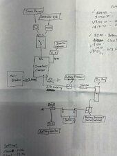
A few posts up I posted a diagram. From what you typed and the diagram. They are not the same the way I'm reading it? Why is the generator last? And not also ran to the auto trasmnsfer switch?Just for clarification, I'm not sure that the original question of how to route the AC circuits has been answered. I've done two Multiplus installs, one in a simple 30 amp system where I did everything and the other was a 50 amp split system where I handled the DC side of things. In both installs the order was like this:
Shore Power -> |\
| -> Transfer Switch -> Multiplus -> RV Main Distribution Panel
Generator -> |/
A few posts up I posted a diagram. From what you typed and the diagram. They are not the same the way I'm reading it? Why is the generator last? And not also ran to the auto trasmnsfer switch?
I'm guessing that's how the factory has it set up on our rvs? I haven't dived into opening anything up.I added periods to get things to line up more intuitively.
.Shore Power -> |\
..................................| -> Transfer Switch -> Multiplus -> RV Main Distribution Panel
......Generator -> |/
His diagram shows both shore and generator as inputs into the transfer switch
The forum software munged the diagram and reformatted it into making no sense. Here's an image of what my diagram should look like.A few posts up I posted a diagram. From what you typed and the diagram. They are not the same the way I'm reading it? Why is the generator last? And not also ran to the auto trasmnsfer switch?

I'm guessing that's how the factory has it set up on our rvs? I haven't dived into opening anything up.
I guess im.not follow still what your saying. Shore power runs into transfer switch as input, run as output from transfer switch to multiplus, out the multiplus to my rv main panel. Then you have the generator also running to the rv main panel? When I turn my generator on it runs for 30 second. Then I hear a loud clunk and then the rv has power. So I know it runs to the transfer switch
Okay yupp that makes sense and is how the drawing is.The forum software munged the diagram and reformatted it into making no sense. Here's an image of what my diagram should look like.
View attachment 206967