diy solar

diy solar

Affordable 24v DC to 24v DC chargers?

jeffc2021

New Member
Joined
Nov 30, 2021
Messages
34
I have a 24v 230ah main battery bank and a separate 24v 100ah auxillary battery, both LiFePo4 with BMS protection. I will be using the auxiliary battery to charge up somewhere else, then bring it back to charge the main battery. I would like to use a DC to DC charger for a better efficiency charging since power conservation is important, and at the same time be cost efficient.

Does anyone know of an affordable 24v DC to DC charger? It doesn't have tobe fast, so 10 amps is fine.
 
All you really need to do is connect the two batteries in parallel with a current limiting device and a fuse for safety.
There's plenty of voltage and current adjustable boost converters on Aliexpress that would do the job - you'd just set it to limit current to your desired maximum, and maybe boost the voltage a little.
Since the smaller battery is going to be regularly disconnected and reconnected at a higher charge, if I install a current limit to the smaller battery, will a constant current be flowing from the higher charge battery to the lower charge battery until they are equal? So would the current limiter act like a DC - DC charger? Also, will the current limiter also limit how much load I can draw, assuming the same setup where both batteries are in parallel?
 
Victron has a couple -


With the smart one you can set (via Bluetooth on your phone), the exact charging specs you want.

I believe (but I am not sure) that it will boost the voltage so the charging is correct. But I never run my 12v one that way - I only ever run it when the engine is on.

Yes. That's a buck-boost converter, which is what you need.

I would also probably just try a high-power resistor, which is not going to be as efficient initially, but the voltages are going to equalize pretty quickly, since one battery is charging, and one is discharging.
 
If I install a current limit to the smaller battery, will a constant current be flowing from the higher charge battery to the lower charge battery until they are equal?
If you're using the boost converter to both increase the charging voltage and limit current, then yes, the current will be fairly constant until the battery you're charging approaches the voltage of the boost converter. Then other factors come into play like the various resistances in the circuit and cells, and the battery's ability to accept any more charge.
Also, will the current limiter also limit how much load I can draw, assuming the same setup where both batteries are in parallel?
It shouldn't - I imagine your load is connected directly to the main battery that's being charged, so your load can draw as much as the main battery can provide, plus whatever current limit you've set on the boost converter from the secondary battery.


I would also probably just try a high-power resistor, which is not going to be as efficient initially, but the voltages are going to equalize pretty quickly, since one battery is charging, and one is discharging.
Some quick math suggests this wouldn't be a good idea - assuming one battery is on the low side (about 23V) and the other is full (29V), you'd be dumping 180W of heat when charging at 30A. That would need to be a big resistor and heat sink!
 
Some quick math suggests this wouldn't be a good idea - assuming one battery is on the low side (about 23V) and the other is full (29V), you'd be dumping 180W of heat when charging at 30A. That would need to be a big resistor and heat sink!

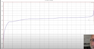
Some actual charge/discharge plots (taken from an "Andy" video) tell a very different story. They show the actual voltage for one cell charging at 40A and the same cell discharging at 40A. If you fully discharge the receiving battery, then you will have a fairly large voltage (4V max?) difference, but only for a very short time, and they very quickly reach almost the same voltage.

It's hard to tell the exact voltage, but it looks to me like it's less than 100mV when both curves hit the knee, which would be less than 1V for the entire battery. Even at the most extreme, the difference is only around 0.5V/cell, but that's only for a very short time. A cheap 100W resistor with no heatsink could handle that.

It looks like the voltages equalize at around 3.3V maybe 15% through the charge, which means, even without the resistor, the current will be less than 40A, and will start tapering off.

1702703457636.png

1702703471785.png
 
Some actual charge/discharge plots (taken from an "Andy" video) tell a very different story. They show the actual voltage for one cell charging at 40A and the same cell discharging at 40A. If you fully discharge the receiving battery, then you will have a fairly large voltage (4V max?) difference, but only for a very short time, and they very quickly reach almost the same voltage.

It's hard to tell the exact voltage, but it looks to me like it's less than 100mV when both curves hit the knee, which would be less than 1V for the entire battery. Even at the most extreme, the difference is only around 0.5V/cell, but that's only for a very short time. A cheap 100W resistor with no heatsink could handle that.

It looks like the voltages equalize at around 3.3V maybe 15% through the charge, which means, even without the resistor, the current will be less than 40A, and will start tapering off.

View attachment 183287

View attachment 183288
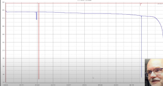
That's true, the heat output from the resister would reduce quite a bit once the batteries are outside their extremes of SOC, but so then would the rate of charge. There's little need to debate this as Andy had also tested this scenario:

TLDW: About 50A for a few minutes, followed by current dropping off very quickly. After quite some time the SOC of both batteries had changed <10% with the current so low that they'd never really transfer a meaningful amount of energy.

So you'd probably end up with a burnt resistor, and even if it did survive, the main battery would receive very little charge. This is why a boost converter with current limiting is necessary.
 
Is the problem too much current, or not enough?

What Andy shows is that it actually does work, although I would use a current limiting resistor to limit the initial surge with SOCs that are very different.

Is a regulated power supply better? Of course, but the OP asked for cheap, and wasn't concerned about particularly high current.

I'm curious what boost regulator you've used for this, and what voltage you set the output at. Typically a boost regulator requires a lower input voltage than the output voltage. You would need a regulator that had a pretty low differential to not have to set the output voltage too high, which is why it seems like a buck/boost regulator would be required.
 
I've used one of these before: https://www.aliexpress.com/item/100...o.order_list.order_list_main.5.75381802N6p20V

Assuming we have two batteries (source and destination):
  1. With only the source battery connected to the boost converter, using a multimeter, the output voltage can be adjusted to the maximum the destination battery would need (i.e. 29V in a 8S LiFePO4 system) and the output current limit wound all the way down to the lowest setting to begin with.
  2. Once the destination battery is connected to the boost converter output, the current limit can be increased to meet a desired maximum. The current can be monitored using an in-line amp meter, or through the destination battery's BMS (which is essential for charging, as always).
The voltage of the source battery will drop throughout the charge, leaving a big enough delta between each battery for the boost converter to do its job. Bucking isn't required at any stage of the charge process.
 
Back
Top