diy solar

diy solar

AiLi battery monitor wiring issues with inverter

Whatever small fuse you have handy. I believe I used 1A on mine since I had some
@Bob142 and @solarstuff I am at this point now myself and was also going to use 12ga wire but it’s overkill? So 18ga? And how do I connect a fuse? Link to what I need? Thanks.
 
@Bob142 and @solarstuff I am at this point now myself and was also going to use 12ga wire but it’s overkill? So 18ga? And how do I connect a fuse? Link to what I need? Thanks.
Yeah, 12ga wire won't fit.

I use 18 AWG in-line ATC blade fuse holders. (Search for them on eBay/Amazon etc.)
Just crimp a ring terminal on one side to connect to your battery/busbar post.
Assuming the shunt is further away from the post than a few inches, use a butt connector or closed end connector to crimp the other side of the fuse holder to an 18 AWG wire long enough to reach the screw terminal on the shunt board. The part of the wire that goes into the screw terminal is just bare wire.

(Click on the Yeti link in my signature and you can see in the first picture the inline fuse holder on the top right with the ring terminal connection to the battery pack positive and a butt connector to the additional wire that runs down to the shunt connection - that connection is hidden from view.)
 
(Search for them on eBay/Amazon etc.)
I see some on Amazon in packs of like 5 or 10. Is 18ga size something that's handy to have a few of? Will really only has 12ga under his "DC Load Hook Up Wire" section. That's why I was thinking 12ga and probably same with solarstuff. Like "might as well go 12 because you know it'll cover you for most of the DC stuff." But if the 12ga wire literally will not fit in the screw terminal then that answers that.
 
@Bob142 and @solarstuff I am at this point now myself and was also going to use 12ga wire but it’s overkill? So 18ga? And how do I connect a fuse? Link to what I need? Thanks.
If you have a DC Fuse box/distribution panel, you can tie it in to one of the fuses there. Otherwise, an in-line fuse is a good option.

The amount of current needed to run the meter is tiny. 12AWG is way bigger than needed. It would work but as Bob142 said, it will be hard to connect to the green connector on the Shunt.
 
I see some on Amazon in packs of like 5 or 10. Is 18ga size something that's handy to have a few of? Will really only has 12ga under his "DC Load Hook Up Wire" section. That's why I was thinking 12ga and probably same with solarstuff. Like "might as well go 12 because you know it'll cover you for most of the DC stuff." But if the 12ga wire literally will not fit in the screw terminal then that answers that.

I find a lot of places where 18AWG is the best solution. Having some extra 18AWG fuse holder and wire is a good thing.
 
I see some on Amazon in packs of like 5 or 10. Is 18ga size something that's handy to have a few of? Will really only has 12ga under his "DC Load Hook Up Wire" section. That's why I was thinking 12ga and probably same with solarstuff. Like "might as well go 12 because you know it'll cover you for most of the DC stuff." But if the 12ga wire literally will not fit in the screw terminal then that answers that.
If you happened to already have some 12 AWG fuse holders handy, or need to buy a pack for other needs, there's no issue with using one here. Just use a closed end connector to crimp that and 18 AWG wire together. As long as the fuse is small enough to protect the 18 AWG wire, it works fine. (Since I have 4 systems that all use a shunt battery monitor I bought a pack of 18 AWG fuse holders.)
 
Just use a closed end connector to crimp that and 18 AWG wire together.
I have done this myself and it can be made to work. However, the 12AWG wire will tend to put stress on the green connector that it was not designed for. In general, it is best to properly size the wire.
 
I have done this myself and it can be made to work. However, the 12AWG wire will tend to put stress on the green connector that it was not designed for. In general, it is best to properly size the wire.
That's what the 18 AWG wire crimped to the 12 AWG in-line fuse holder is for. The 18 AWG wire goes to the shunt screw terminal. The 12 AWG wire goes to the positive battery/busbar post.
 
I happened be near an autozone and Oreilly’s and neither had a fuse below 2 or 3A nor an 18ga inline fuse holder. Where did people buy stuff pre ebay and amazon? Maybe radio shack. They did have 18ga wire but I was afraid it could be junk because it didn’t have the word “copper” anywhere on it. Will talks about amazon being full of like copper coated aluminum wire.
 
I happened be near an autozone and Oreilly’s and neither had a fuse below 2 or 3A nor an 18ga inline fuse holder. Where did people buy stuff pre ebay and amazon? Maybe radio shack. They did have 18ga wire but I was afraid it could be junk because it didn’t have the word “copper” anywhere on it. Will talks about amazon being full of like copper coated aluminum wire.
Yup, Radio Shack.
 
I happened be near an autozone and Oreilly’s and neither had a fuse below 2 or 3A nor an 18ga inline fuse holder.
Even with 18AWG a 2A fuse would probably work OK. A 1A would be better.
 
That's what the 18 AWG wire crimped to the 12 AWG in-line fuse holder is for. The 18 AWG wire goes to the shunt screw terminal. The 12 AWG wire goes to the positive battery/busbar post.
Sorry, I just re-read your post and I had originally miss-understood it. Yes, reducing the wire size to 18AWG would work fine.
BTW: The meter uses this connection to measure the battery voltage. (that is how it knows Wattage). For things like this where accurate voltage measurement is important, *any* resistance can be very bad. Consequently, I would tend to do a solder connection between the 12 and 18 AWG and then cover it with heat shrink.
 
Just for my education, how do you know that 18ga and a 1A fuse is the right size? Is there a spec for the power the shunt uses?
 
I measured it once but don't remember the exact value, All I remember is that it was small. (Unfortunately I don't have one handy to do the measurement again.)

Keep in mind that the fuse is to prevent fires in case of a short. A 1A fuse will blow before the 18AWG burns.
 
I measured it once but don't remember the exact value, All I remember is that it was small. (Unfortunately I don't have one handy to do the measurement again.)

Keep in mind that the fuse is to prevent fires in case of a short. A 1A fuse will blow before the 18AWG burns.
62D96FD0-D368-4423-9056-71E72BEED65F.jpeg949899DE-F002-44C8-978E-361B1B6CDE74.jpeg
 
There is one rule for sizing fuses. #1. Fuse protect wire. 18 awg wire is fine with a 20 amp current. So any fuse smaller than 20 will protect the 18awg wire.
 
I am not sure what you are asking, but I *think* the answer is no. If I am understanding your set-up, this is what is should look like. View attachment 6622 Note: If the main fuse on the battery is small enough to protect whatever gauge wire is going to the inverter, the additional fuse on the positive to the inverter *may* not be needed but it is still a good idea to have if the max current to/from the inverter is less than the main battery fuse. Also, if the inverter does not have some type of over-current protect built in, there should be another fuse or breaker on the positive close to the inverter. A few guidelines for fusing: * All current sources should have a some form of over-current protection in them or right next to them. * The fuse should be rated at 125% of the max power expected on the smallest wire in the circuit the fuse is intended to protect. * Anytime a smaller wire connects to a larger wire, it should probably be fused.
 
Please provide a diagram of your set-up.

Is the inverter negative on the B- or P- side of the shunt. If it is on the B- side of the shunt, the shunt can not measure current going to/from the inverter.

Yes, the P- will typically go to chassis and, in you case it sounds like that is also the negative return for all of your devices except your inverter. That means the shunt is measuring the current to/from all of the devices except the inverter.

As a side note: chassis ground is not typically considered a good path for the negative connections to appliances/devices. If I am understanding your set-up you are putting a heavy gauge wire between the inverter and the battery negative. That is good but it needs to be to the P- of the shunt, not B-

Edited to add comment about gauge
You may want to consider adding a negative return wire for all of your other devices as well. (They should be the same gauge as the positive wire to the device) You should at least consider doing it for any high current devices you might have on the circuit.

BTW: In my drawing above, I notice I show the fuse on the negative side. That works but I typically put the fuse/breaker on the positive side. (I started with a drawing I had from helping another guy that had the fuse on the negative.) Here is how I more typically would do it:

View attachment 6619
Notice that the tiny positive wire to the shunt is fused seperately. The main fuse would not even notice a short on the tiny wire going to the shunt. Without the device fuse the tiny wire could become a very smoky fire-prone fuse.

There have been complaints about not showing proper fusing in diagrams so I am trying (and typically failing) to remember to do that. Whenever you see a diagram from any of us, don't assume the fusing is correct. If you are not sure how something should be fused, ask.
What size fuse???
 
I am not sure what you are asking, but I *think* the answer is no. If I am understanding your set-up, this is what is should look like.


View attachment 6622

Note: If the main fuse on the battery is small enough to protect whatever gauge wire is going to the inverter, the additional fuse on the positive to the inverter *may* not be needed but it is still a good idea to have if the max current to/from the inverter is less than the main battery fuse. Also, if the inverter does not have some type of over-current protect built in, there should be another fuse or breaker on the positive close to the inverter.

A few guidelines for fusing:
* All current sources should have a some form of over-current protection in them or right next to them.
* The fuse should be rated at 125% of the max power expected on the smallest wire in the circuit the fuse is intended to protect.
* Anytime a smaller wire connects to a larger wire, it should probably be fused.
What size fuse
 
What size fuse
Sorry.... I have been on the road and have had limited time and limited internet access.

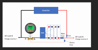
Just to be sure what fuse we are talking about, Lets use this diagram:

1605595119907.png
Te 'device fuse' should be something small. 1A would be good. You could get away with a 2A or even 3 A fuse. This fuse should be as close to far end of the wire going to the shunt as possible.

The 'main fuse' should be your total expected max load plus ~20%. (Note that the inverter can have very large surge currents. With inverters, I tend make the main fuse more like 50% more than the expected stead state load. This is lower that the surge current, but as long as it is not a fast-blow fuse, it works fine). In any case, make sure any wiring between the main fuse and either a device (or another fuse) can handle the current rating of the fuse. This fuse should be as close to the battery as possible.

The one just labeled 'fuse' is the one I was referring to in my previous post.
*If the wire going to the inverter is big enough to handle the current rating of the 'main' fuse, you could get away with just the main fuse and not have an inverter fuse. If the inverter is your only load, this is perfectly acceptable.

* if you have other loads besides the inverter, it is best to put in a fuse specifically for the inverter and size it according to the manufacturers spec or 50% more than the continuous load rating of the inverter. This fuse should be as close to the main fuse as possible.
 
Sorry.... I have been on the road and have had limited time and limited internet access.

Just to be sure what fuse we are talking about, Lets use this diagram:

View attachment 27780
Te 'device fuse' should be something small. 1A would be good. You could get away with a 2A or even 3 A fuse. This fuse should be as close to far end of the wire going to the shunt as possible.

The 'main fuse' should be your total expected max load plus ~20%. (Note that the inverter can have very large surge currents. With inverters, I tend make the main fuse more like 50% more than the expected stead state load. This is lower that the surge current, but as long as it is not a fast-blow fuse, it works fine). In any case, make sure any wiring between the main fuse and either a device (or another fuse) can handle the current rating of the fuse. This fuse should be as close to the battery as possible.

The one just labeled 'fuse' is the one I was referring to in my previous post.
*If the wire going to the inverter is big enough to handle the current rating of the 'main' fuse, you could get away with just the main fuse and not have an inverter fuse. If the inverter is your only load, this is perfectly acceptable.

* if you have other loads besides the inverter, it is best to put in a fuse specifically for the inverter and size it according to the manufacturers spec or 50% more than the continuous load rating of the inverter. This fuse should be as close to the main fuse as possible.
Device fuse
 

diy solar

diy solar
Back
Top