diy solar

diy solar

Am I detecting a trend to HV-battery inverters and, if so, what will that mean for us DIYers long term?

SeaGal

Photon Sorceress
Joined
Aug 17, 2022
Messages
2,642
Location
UK
Pretty much as the title says...

Obviously inverters that operate with HV batteries are not new, but I seem to be noticing them more now than 18 months ago. Is it just me, or is that the way the industry is going?

My concern is whether such a trend (if it indeed exists) will result in more proprietary solutions that make it harder for us DIYers to build our systems.

What triggered me to start this thread, is hearing of (in the UK) a FoxESS system being proposed that had a strange battery capacity of 2.9kWh. When I looked into it, it referenced a nominal battery voltage of 57.6V. My first reaction was "what chemistry", but their brochures stated LFP - which fits an 18s architecture. It seems FoxESS have a stackable HV solution of between 2 and 7 "units" of 2.9kWh, with voltage range of 115V to 403V. Proprietary, or what? :unsure: :(
 
  • Like
Reactions: JRH
I think it is getting to be pretty common.

SMA Sunny Boy Storage (AC coupled battery) has a list of supported batteries. Sunny Boy Smart Energy I think only lists BYD right now but should also support many brands. Voltage something like 100V to 500V.

This lets battery design be series stackable for a range of kWh, uses skinny wires.
They will support a number of protocols, just like the 48V BMS ones do. But I don't think we will be able to set inverter to "VRLA" and fake it. Similarly, won't be able to connect HV string of lead-acid; without communications it won't dare drive anything.

Even though HV battery home inverter have been out for several years, I'm not aware of any BMS for DIY documented as supporting them. There are several BMS that can be connected for HV, like up to 128s, but I don't know if they will talk.

The trend in US is to require UL listed ESS, being paired inverter and battery models, which certainly isn't DIY friendly. But makes some sense, since the inverter is perfectly capable of blowing out BMS and overcharging battery. (except for battery with HV DC/DC converter.)
 
Yes indeed.
Grid tie inverters are all high dc input voltage types.
And so are electric vehicles.
More efficient smaller fully sealed cells also encourage stacking more smaller cells in series.
Faster, more efficient semiconductor devices that work well at higher voltages are now more readily available at reasonable cost too.

That is the way its all evolving, higher voltages at reduced current, for higher power levels and better overall efficiency.
 
If high voltage DC were a thing I would be all over it. Just think what you could do with #10 and smaller.
Biggest hurdle is probably going to be the switching. Lots of arc with DC.
 
Soft start circuits (precharges capacitive load), and "power good" output to enable downstream circuits.
Those are already a thing even at low voltage. (must be done right to work, of course)

HV has been the way for UPS, for years. While some units had a single 12V battery, others had four in series for 48V, and larger systems had hundreds of volts.

Our industry using low voltage probably came out of its early off-grid days. The GT PV inverters just worked at high voltage, as mentioned above. Earlier ones required minimum MPPT voltage higher than AC Vpp, but newer ones accept a wide range (probably have HF transformer, or could be buck/boost SMPS but I think that has more losses.)
 
Think about dc traction motors and the railway system.
Sometimes tens of Kv, and thousands of amps, and the circuitry required for speed control is solid state these days.
Pretty extreme stuff, but the technology not only exists, its been around for a long time.
 
Long ago, the PV voltages were low voltage,, but high voltage took over as it was the technically better choice ( smaller wires, lower currents ).

The gridtie inverters and charge controllers also started low voltage and now most are in the 500-600V range

Storage systems are following a similar path, and for the same reasons, the balance of system costs ( wire and all that makes the connections ) are substantially less when the operating currents are about 1/8th that of 48 volt battery banks.

The issue in the US is storage is new and with UL regulations, closed loop communications is the norm for HV systems. That said there are options for DYI, most inverters use the Pylontech HV protocol and there are also High voltage BMS solutions as well for DYI

If history repeats, I expect just the power requirements alone meeting the need for partial / whole home backup will have HV options as the cost effective choice. Just price out 4 AUT wire and you will see what I'm writing about.
 
Soft start circuits (precharges capacitive load), and "power good" output to enable downstream circuits.
Those are already a thing even at low voltage. (must be done right to work, of course)

HV has been the way for UPS, for years. While some units had a single 12V battery, others had four in series for 48V, and larger systems had hundreds of volts.

Our industry using low voltage probably came out of its early off-grid days. The GT PV inverters just worked at high voltage, as mentioned above. Earlier ones required minimum MPPT voltage higher than AC Vpp, but newer ones accept a wide range (probably have HF transformer, or could be buck/boost SMPS but I think that has more losses.)
Yep I have a ups with 240volt dc battery bank. Ton of those little 12v ups batteries in series in pull out trays. Thing weighs a TON. I bought it home in a 1/2 ton pickup truck and I knew it was in the bed of the truck. It was wired for 3 phase power when I got it home and had to rewire it.
 
The gridtie inverters and charge controllers also started low voltage and now most are in the 500-600V range

Charge controllers of course started out for 12V off-grid systems (may have been a few other niche applications prior.)

I think SMA invented the grid-tie PV inverter, and introduced Sunny Boy. HV PV input, HF switching PWM to synthesize sine wave, LF isolation transformer.

Likely the first grid-tie hybrids were a reprogramming of LV "LF" transformer-type 12V or 48V off-grid inverters. I think Outback had GTVF at the time I got my Sunny Boys. AES was another, a hybrid.


My earlier Sunny Boys were 600V max, with a minimum voltage I think of 250V. Transformer isolated, could boost to the 340Vpp of 240VAC. The first transformerless (pure HF) Sunny Boys required minimum PV voltage higher than AC Vpp. later ones allow wider PV voltage range.

Wide PV voltage range and multiple MPPT better supports residential rooftop install. Didn't matter for commercial scale.

Same architecture probably used for the battery and hybrid models (but those do need bidirectional DC to battery.) If same MOSFETs are simply enable to drive power in opposite direction, that enables some interesting risk/failure modes for PV systems. Wide range of battery voltage supports wider kWh range for a given battery cell size, configurable products, upgradeable systems. The specs call for higher kWh and battery voltage to support higher kW inverter output. Surge capability also limited by those (but opportunities exist for creative product designers.)
 
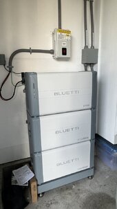
I think similar to what I am setting up. Of course, they are closed-loop but simple to set up and easier to permit and all UL listed

Bluetti.jpg
 
Hi SeaGal, yes, I've noticed a shift towards HV too and I've only been looking into PV for about 18m! Fox Mira ESS, Solaredge 10kW battery, also as another poster said BYD for SMA. Seems to me that inverter and/or battery companies desire to move to all in one systems so they can sell you both. Or is there feed across from automotive? Victron don't appear to be pushing the residential market, although the 10kW Multiplus has been approved on ENA recently which seems to me would suit larger installs.
 
A 50A semiconductor is cheaper and more efficient (less heat lost) than a 200A semiconductor. So higher voltages will always be preferred. Stronger magnetic fields with less copper, again another bonus. This on top of wires that are 1/10 the copper of our low voltage systems for the same power output.

DC arcing really doesn't change the design of switches and other components until after a few hundred volts. So there will be some, but not very much, change going from, say, 48VDC to 480VDC in terms of arc quenching and conductor insulation/distances.

The bigger difference is the regulatory and safety aspects, but the NEC and industry pretty much require the same safety and interlocks for low voltage DC as for high voltage DC - witness the metal conduit for all indoor DC power circuits related to batteries and solar panels, even if the voltage is low.

So there's little downside, and lots of upside.

I expect the DIY'ers to evolve. There are plenty of DIY'ers involved in high voltage vehicle systems repurposing tesla, nissan, and other electric drivetrains in their custom vehicles. They've figured out the communication and safety aspects, and we will too, as needed.
 
There is a safety threshold at 100VDC in the US with regards to how much exposed wire is allowed in areas that require service when energized. < 100VDC it's pretty lax, > 100 VDC invites lots of scrutiny.

Personally I don't think it's a huge deal, you don't want to stick your fingers in those situations anyway. But it will require some adjustments to wiring best practices.

I also think it invites more crossover of expertise between DIY EV and Solar / ESS
 
Back
Top