diy solar

diy solar

Ampere Time 48v System Design from 12V 200Ah Batteries

TurbineTester

New Member
Joined
Apr 1, 2021
Messages
143
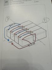
As the title suggests i'm assembling a 48v system for my Motorhome. I have 8 12v 200Ah Ampere Time Batteries with 100A BMS. To help with space in the bays of the RV, I’m putting 4 batteries on the passenger side bay and 4 on a drivers side bay. I had been thinking of 4 batteries in series (4s) on the left and 4s on the right, and then putting the two sides in parallel (2p). This would give me 48v 400Ah. There is a picture in the manual of how to do this, but the picture has the two 4s strings right next to each other and every negative and positive battery post is connected across the two strings. See the diagram. My two bays are separated by about 3-4 feet. So that would be quite a lot of wire going across the bays (presumably to help aid in balance the batteries). It also seems like the diagram is a little excessive in the use of cables across the like polarity terminals. This would be physically splitting the system at dashed line A. The other thing I thought of is to make two 24v banks, one on each side of the RV, and those two 24V banks in series. This would be like physically splitting the system on dashed line B. This would be much simpler as only two wires would be needed to go across the gap between the bays. Again because of space, in each bay I’m planning on stacking the batteries 2x2, kind of making battery cube. That way I can use a bus bar to connect a + and - post across that short distance instead of making a tiny cable. So at this point I’m kind of leaning towards a 24v bank on each side.


I will use a 48V Inverter/Mppt controller (thinking the 3000w Growatt at this point) to charge the bank from Solar and to power my high amp items like microwave and one of my AC units, and also have a 48v/12v DCDC converter to allow the 48v bank to maintain the 2x12v BattleBorn Batteries I have for my 12v house system.


So my questions are:


Which layout is best? 2x24v banks or 2x48V banks?


What is the best readily available material at Lowes/HD/Amazon should I use to cut/drill the short bus connections?


I see T fuses mentioned a good bit in the forum when discussing series/parallel banks. Where might I need them?


What other questions should I be asking at this point?


Thanks
 

Attachments

  • IMG_8673.jpeg
    IMG_8673.jpeg
    101.6 KB · Views: 8
If you are only running a 3kw inverter, why jump up to 48v? 3000w on a 12v system is still very reasonable in terms of current. I think in your case, you are at the point where you will have a lot more cost and complication going up to 48v, such as adding balancers and DC-DC converters. If you stuck with 12v, then you would just parallel all batteries on both sides and then run an equal length set of cables from each side to your bus bar - now you have perfect current sharing and perfect balancing...

Might be worth reconsidering!
That's certainly worth considering but the downside is the high amp draw on a 12v system. I should have pointed out that the 3000w inverter is the second inverter on this coach. There is already a Magnum 12v 2000w inverter that currently runs the most of the coach. It will run the microwave, but it's a real strain on the system, coffee pot is the same problem. So, i'm really looking for 3000w of additional inverting capacity for high amp loads like microwave, coffee pot and one roof top AC. Given those loads i'm trying to keep amps low. Does that complicate matters even more? :)
 
That's certainly worth considering but the downside is the high amp draw on a 12v system. I should have pointed out that the 3000w inverter is the second inverter on this coach. There is already a Magnum 12v 2000w inverter that currently runs the most of the coach. It will run the microwave, but it's a real strain on the system, coffee pot is the same problem. So, i'm really looking for 3000w of additional inverting capacity for high amp loads like microwave, coffee pot and one roof top AC. Given those loads i'm trying to keep amps low. Does that complicate matters even more? :)
Absolutely does! In my opinion, you would be far better off consolidating down to a single 5000w inverter if you are sticking with the 48v system.
 
If you must use 12v batteries to produce a 48 volt pack, build two separate 4 battery packs, each 48v, use battery balancers, and a suitable 'master' classT fuse
Connect in parallel after the fuses
Don't follow the connections in your diagram .

That's a lot of battery capacity, how will you charge them?

Mike
 
I would never recommend using BMS's in series.
If you can replace them with the correct voltage battery. That's what you should do.
But if you have already purchased them. And can't return them. You definitely need a couple of battery balancers. And go with two separate packs.
 
Assuming you haven't already purchased the 12V batteries, it would be MUCH easier to swap them for 48V if that's what you want to run with the inverter.
There is a picture of the 12V models saying it can run up to 4P4S but that's a much more expensive and sensitive wiring configuration than just using 48V batteries.

You also mentioned using a flat bar for connecting the physical batteries rather than short cables. That's going to be a PITA inside the battery bays and will probably end up as a physical failure point.

In your planned configuration, any single 12v battery issue renders your bank unusable.
If you start with 48V batteries and have an issue with one of them, you can simply turn it off and continue to run from the rest of the bank til you get it fixed.
 
Absolutely does! In my opinion, you would be far better off consolidating down to a single 5000w inverter if you are sticking with the 48v system.
That would be nice but i already need a 12V system for the RV "house" 12v needs, and most of it is already wired for the 2000w inverter. I am only going to power the high amp draw items from the 3000w inverter.
 
If you must use 12v batteries to produce a 48 volt pack, build two separate 4 battery packs, each 48v, use battery balancers, and a suitable 'master' classT fuse
Connect in parallel after the fuses
Don't follow the connections in your diagram .

That's a lot of battery capacity, how will you charge them?

Mike
Thank you so much for your reply. Where would i put the master t-fuse?

Is this model balancer well known enough or would you recommend another?

I will charge them through the inverter with the generator/shore power when available, solar power otherwise. I'd like to look into adding or configuring a 48v alternator to the F53 chasis system as well. I don't think i have enough time to do that before we leave for a 6 week trip on June 9.
 
I would never recommend using BMS's in series.
If you can replace them with the correct voltage battery. That's what you should do.
But if you have already purchased them. And can't return them. You definitely need a couple of battery balancers. And go with two separate packs.
Yep, hindsight and all. I started with a 2 battle born 12v lithiums, then added 3 additional 12v200Ah Ampere time lithiums for extra capacity, and that worked for a trip last summer but i didn't like the physical layout and i had room for 5 more batteries so that's what i ordered as the 48v batteries were either a) significant'y more expensive per watt*hour or b)out of stock. So i have room to nicely fit a 2x2 battery stack on each side of the coach.
 
Assuming you haven't already purchased the 12V batteries, it would be MUCH easier to swap them for 48V if that's what you want to run with the inverter.
There is a picture of the 12V models saying it can run up to 4P4S but that's a much more expensive and sensitive wiring configuration than just using 48V batteries.

You also mentioned using a flat bar for connecting the physical batteries rather than short cables. That's going to be a PITA inside the battery bays and will probably end up as a physical failure point.

In your planned configuration, any single 12v battery issue renders your bank unusable.
If you start with 48V batteries and have an issue with one of them, you can simply turn it off and continue to run from the rest of the bank til you get it fixed.
I understand and wish i had done things different at this point. However, this is what i have. Regarding the bus bars I can easily build a rack (two actually) out of cabinet grade plywood to secure the batteries against movement relative to each other and within the bay. So my thinking was that the 4 batteries on each side would be just as rigidly fixed to each other as cells inside a DIY battery.
 
Class T fuse at each 48v pack before batteries are paralleled.
Balancer seems OK and good value.
Use cable to series connect the batteries, no matter how well you construct a battery mounting frame there will be differential slight movement between batteries, also its probable the dimensions of the battery's differ with respect to terminal positioning .
 
Last edited:
Class T fuse at each 48v pack before batteries are paralleled.
Balancer seems OK and good value.
Use cable to series connect the batteries, no matter how well you construct a battery mounting frame there will be differential slight movement between batteries, also its probable the dimensions of the battery's differ with respect to terminal positioning .
Ok good deal will do on the cables and the balancers.
 
Class T fuse at each 48v pack before batteries are paralleled.
Balancer seems OK and good value.
Use cable to series connect the batteries, no matter how well you construct a battery mounting frame there will be differential slight movement between batteries, also its probable the dimensions of the battery's differ with respect to terminal positioning .
And the t-class fuse should be sized for the cable going from each battery bank to parallel connection point? So if i anticipate a potentially 5000w inverter that would be around 100A at max current, less 20% effeciency puts it at about 125A, so 4 ga cable and a 125 or 150A t class fuse? Out of curiosity, why a t-class fuse and not a 150A DC circuit breaker? If i'm in the middle of nowhere and loose a fuse i have to get another one shipped if i don't have spares on hand ( which i will), but a breaker can be nearly instantly reset...
 
I've got this balancer for a setup similar to yours. I like having the voltage readouts, even if they only go one decimal point.

61OGfL+mv+L._SL1500_.jpg
 
Buy an extra fuse or two, very few breakers can meet the 20,000 amp withstand of a class T fuse.
The reason for a classT is to prevent the very high currents, in the region of several thousand amps, that could flow under fault conditions , that would spoil your day.
Hopefully the BMS in one or more of the series batteries would enter protection and stop the current flow, but if the BMS were to fail, the fuse is the last line of defence.
Ok that makes a lot of sense. Could you possibly link me to one that would be suitable? The T Class fuses i saw in a cursory glance on Amazon were in the 125A range.
 
There is a 4' gap between my left bank and my right bank of batteries. I'm trying to determine how concerned i should be about equal wire lengths from the bank to the inverter. Resistance of 4ga stranded copper is in the neighborhood of .0002485 Ohms per foot and i'm entertaining a wire length differential of 4' from the right bank to the left bank. It would be a voltage difference measured in thousandths of a volt if i'm doing my math correct, and that seems fairly insignificant. How concerned do i need to be about equal wire lengths between each 48v bank and the inverter?
 
There is a 4' gap between my left bank and my right bank of batteries. I'm trying to determine how concerned i should be about equal wire lengths from the bank to the inverter. Resistance of 4ga stranded copper is in the neighborhood of .0002485 Ohms per foot and i'm entertaining a wire length differential of 4' from the right bank to the left bank. It would be a voltage difference measured in thousandths of a volt if i'm doing my math correct, and that seems fairly insignificant. How concerned do i need to be about equal wire lengths between each 48v bank and the inverter?
4' would be pretty significant. Unless the total length is 40'.
Will it still work pretty close to balanced, maybe.
But, you will be able to see the difference during charging and discharging.
Note: no matter how hard you try. It will never be perfectly balanced. All you can do is try to not make it worse.
 
Back
Top