diy solar

diy solar

Axpert Max ii 8kw: use grid as generator and control with program 12 and 13

Kurtbe

New Member
Joined
Nov 23, 2023
Messages
9
Location
Ghent Belgium / Valencia Spain
I am looking to configure an Axpert max ii 8kW in a way that it will not take its own power from the grid. The house if often empty for months, and therefor there is hardly any need for power during this time. But if the Axpert takes it's own power from the grid (which it DOES @70W), then my normal bill would rise instead of going down with a solar system.
Therefor I have disconnected the grid using the dry contact and connected the grid to a relais which will kick in at low battery value and disconnect when battery has regained some energy from the grid @10Amps.

This would typically be in the morning. If the battery goes under let's say 15% then I want the grid to kick in and top up the battery to let's say 30% (or maybe 50). That should be enough, because soon after the sun will start charging the batteries.

Programs 12 & 13 allow me to set these values, but based on Voltage which is very unreliable and varies wildly.
Does anybody know of a way to achieve this with more accuracy? (My Victrons in other installations allow this based on SOC, which is quite accurate), but the Axpert does not seem to be capable to do that.

So, if any body knows how to finetune programs 12 & 13, I would be most grateful, because so far, days of Googling have not provided any solution.

PS: I am not an expert, nor a technician. (But I do have a set of well working brains.)
PS2: I have tested night charging @2Amps-230V (=460Wx8hrs=3680W input) but that only delivered 5% battery gain (480W in 8 hours), 460W input, consumption in house was 90W, + Axpert @70W, leaves 300Wx8hrs=2400W available to put into battery. Yet only 480 were put in. What happended to the other nearly 2000W?


Greetings, Kurt
 
Hello Kurt,

I had a similar problem to solve with my EG4-6500EX inverters (which are based on Axpert Max MKS2-6500). They also have settings 12 & 13 to control when to switch to grid and switch back to battery. They have a self power consumption of 100W and as soon as the grid is connected to the AC-in, the self consumption is split and it draws about 50W from the grid and 50W from the batteries. Because I run 6 of this units in parallel it would consume 300W just to let the grid connected to be prepared for some rare events - like in your situation.

Btw.: Power is measured in Watts and Energy is measured in WattHours (usually kWh). So in my case with six inverters the grid energy consumption would be 6*50W*24h=7.2kWh per day if permanent on grid connected (about 2560 kWh per year).

About triggering program 12&13 based on SOC vs. battery voltage:
Your inverter needs to communicate with the batteries BMS (closed loop communication) to be able to set program 12 & 13 values in SOC units. If no BMS communication between inverter and batteries both programs using battery voltage. Closed loop communication is often a bit tricky because the batteries and the inverters needs to support the same protocol and even if they do, they are not always compatible!

Although I am able to use communication between the inverter and BMS, I don't use it and have found that relying on voltage is not as bad as it seems at first glance. If you are using LiFePO4 (LFP) batteries the SOC which the BMS detects will gets very inaccurate very fast when you don't charge the batteries often to 100% SOC. This is because of the flat voltage curves of LFP batteries and even the BMS inside the batteries is not able detect the current SOC exactly and they need to be "reset" very often and this will be done by fully charging to 100%. If you don't hit 100% SOC very often the SOC reading from the BMS is not a good indicator!

For a scenario where you just want to "survive" the rest of the night from early in the morning (batteries nearly empty) until solar production begins, you will be on the lower side of the SOC of the batteries and in this range you have a steeper voltage curve, also with LFP batteries. Early in the morning you usually have a relatively low and constant load which lets the battery voltage be a good indicator and I found that using voltage settings for programs 12 & 13 works great (for just the described scenario).
  • I close the AC-in relay/contactor if the battery voltage drops below 50.6V (the value is provided via SolarAssistant to control a WiFi Shelly relay to connect the grid). 50.6V on a low moderate discharge rate of about 0.01C-0.1C is about 8% SOC.
  • Setting in program 12 is set to 50V (about 5% SOC for this load scenario) to switch to grid (bypass and grid charging)
  • Setting in program 13 is set to 53V (about 18% SOC for this charging scenario) to switch back to battery

About your missing energy:
It's very likely that your inverters also take only half of it's self consumption from the grid and the other half from the batteries if you just connect the grid. Could it be that your inverter has 2*70=140W self consumption and not only 70W? This would explain at least a part of the missing energy. Also you need to calculate the charging/discharging losses - the battery round-trip efficiency with LFP is about 90% but you also need to calculate the charger losses! Perhaps all of these 3 reasons can explain why energy is missing and where it has gone (in the end it just increased the entropy ;) )
 
Whauw, thank you very much fmeili1.
Such an elaborate answer!
First of all: the missing energy.
Turns out that the 2Amps refers to battery side and so we are talking 98W (@48v) and not 460W (@230V) of power. So that solved that.

Then About triggering Programm 12 & 13:
You clearly understand my question very well! But using the voltage to regulate my 2 LFP Pylontechs 5000 is quite different from the values you provide (but I assume you run on a 110V grid, which could account for any differences).
Normally the batteries get charged to 100% on a daily basis by the PV panels. So SOC should be reliable, besides The SOC in my car is quite reliable and I typically charge the only to 80%.
So far I can only set a round figure of voltage. If I set program 12 to 48V, this will empty the battery to around 3-5%, which I would like to avoid. If I set 49V, then the grid kicks in around 40%, which is way too high. Furthermore, once switched to the grid, program 13 will only allow 51V as the lowest Voltage to return to the battery. Since I charge quite slowly (1kW) I practically never get to that 51 voltage point until the battery is 100% full. So in practice I get a choice between 5% to 100% or 40% to 100%. Whereas I would like to switch between roundabout 15 and 35%.
So far I have no other way to control the dry contact.

PS: the reason for slow charging is because in Spain the price of electricity is somewhat complicated. Up front you have to decide the "potencía" In my case now 9kW. During Covid the house was empty for 2 years. Not a single kWh was consumed. Yet we paid around 40€ per month, because we MIGHT consume up to 9kW. Now they have changed the potencía in two zones: Day time (8-24) and 00 to 8. Night potencía being about 10% of the day time potencía. The price per kWh is also set in 3 different timezones. Ideally I want to have power available between 00 and 08, because it is cheapest. I am therefor looking at setting the daytime potencía to 2kw, and 5kw in the night. The idea being to test the system for a year and see how often I had to fall back to the grid. There is a fair chance that this will never happen, after which I would disconnect from the grid altogether.

The background to disconnect from the grid (and in the mean time pay as little as possible) is because we got fined 4000€ from the electricity company for fiddling with the meter. Their proof being that one month we had a lot of use on the meter, and the next zero. (As one would from a second home.) It took a 3 year legal battle to get our 4000€ back. Now all I want is to get rid of the grid asap.

PS2:
  • Setting in program 12 is ... to grid (bypass and grid charging): what do you mean with "BYPASS AND grid charging"?
Well, I must say that I am looking out for your feedback.

Kind regards, Kurt
 
Whauw, thank you very much fmeili1.
Such an elaborate answer!
First of all: the missing energy.
Turns out that the 2Amps refers to battery side and so we are talking 98W (@48v) and not 460W (@230V) of power. So that solved that.
good
Then About triggering Programm 12 & 13:
You clearly understand my question very well! But using the voltage to regulate my 2 LFP Pylontechs 5000 is quite different from the values you provide (but I assume you run on a 110V grid, which could account for any differences).
Normally the batteries get charged to 100% on a daily basis by the PV panels. So SOC should be reliable, besides The SOC in my car is quite reliable and I typically charge the only to 80%.

So far I can only set a round figure of voltage. If I set program 12 to 48V, this will empty the battery to around 3-5%, which I would like to avoid. If I set 49V, then the grid kicks in around 40%, which is way too high. Furthermore, once switched to the grid, program 13 will only allow 51V as the lowest Voltage to return to the battery. Since I charge quite slowly (1kW) I practically never get to that 51 voltage point until the battery is 100% full. So in practice I get a choice between 5% to 100% or 40% to 100%. Whereas I would like to switch between roundabout 15 and 35%.
So far I have no other way to control the dry contact.
In general, if you want to set the values for programs 12 & 13 in SOC percent unit instead of voltage, you need to setup a communication (RS485) between the inverter and the batteries! To do this, all batteries have to be chained with RJ45 cables and the first needs to be connected to the inverter (in case of many inverters, just to the first). Additionally, program 5 (Battery Type) has to be set to your specific battery protocol - I don't know, if your inverter does support the Pylontech 5000 battery (ask Pylontech and/or Axpert support). If you choose "USE" as user defined battery type, than programs 12 & 13 will use voltage unit to set the trigger levels.

In case you could establish this communication and because you charge your batteries often 100% you could use SOC for program 12 & 13 settings. This would be more fine grained because you could choose values in 5% steps which is a lot better than the 1V steps if no inverter to battery communication is used.

I know exactly your needs when using voltage units in programs 12 & 13 because it only allows 1V steps and this is typically not exact enough for what we want to achieve.

Because I already got the data via SolarAssistant and I can remotely control the AC-in contactor via smart home rules (as I mentioned in my previous post - but until now not in all details), I've solved this by changing the setting for program 13 from 53V automatically to 52V via SolarAssistant if the battery voltage jumps over 52.5 volt. This lets the inverter suddenly stops grid charging (because now the battery voltage is over the setting in program 13). After that, I receive the inverter mode change from "Grid" to "Solar/Battery" in my smart home and adjust the value for program 13 back to the original 53V to be prepared for the next grid charging cycle.

With this "trick" I'm able to use programs 12 and 13 like it would have 0.1V steps available. This only works, because I've already had the remote controlled AC-in contactor, the SolarAssistant which is connected to my smart home system (OpenHAB). SolarAssistant is not only able to monitor the values, you can also change the settings via MQTT command.

PS: the reason for slow charging is because in Spain the price of electricity is somewhat complicated. Up front you have to decide the "potencía" In my case now 9kW. During Covid the house was empty for 2 years. Not a single kWh was consumed. Yet we paid around 40€ per month, because we MIGHT consume up to 9kW. Now they have changed the potencía in two zones: Day time (8-24) and 00 to 8. Night potencía being about 10% of the day time potencía. The price per kWh is also set in 3 different timezones. Ideally I want to have power available between 00 and 08, because it is cheapest. I am therefor looking at setting the daytime potencía to 2kw, and 5kw in the night. The idea being to test the system for a year and see how often I had to fall back to the grid. There is a fair chance that this will never happen, after which I would disconnect from the grid altogether.
interesting billing system
The background to disconnect from the grid (and in the mean time pay as little as possible) is because we got fined 4000€ from the electricity company for fiddling with the meter. Their proof being that one month we had a lot of use on the meter, and the next zero. (As one would from a second home.) It took a 3 year legal battle to get our 4000€ back. Now all I want is to get rid of the grid asap.
unbelievable :oops:
PS2:
  • Setting in program 12 is ... to grid (bypass and grid charging): what do you mean with "BYPASS AND grid charging"?
In case the inverter hit program 12 (point back to utility/grid), it does two things in parallel. First, it triggers it's internal ATS (Automatic Transfer Switch) to connect the AC-out of the inverter to the AC-in to feed the inverters load directly from the grid (the inverter part DC/AC will not be used in this mode and this is called BYPASS). Second, the batteries starting to get charged from the grid with the amperage setting in program 11.
After the setting in program 13 will be triggered, the inverter disconnects the ATS again and uses it's inverter DC/AC unit to drive the load ont the AC-out and stopping grid charging of the batteries.
Well, I must say that I am looking out for your feedback.

Kind regards, Kurt
Frank
 
Last edited:
Hello frank, pleased to make your acquaintance.
And again thank you for your answer.
In general, if you want to set the values for programs 12 & 13 in SOC percent unit instead of voltage, you need to setup a communication (RS485) between the inverter and the batteries!
All this has been done. And program 5 has been set to PYL.
After reading your info I am left with a bundle of questions...
  • In case you could establish this communication and because you charge your batteries often 100% you could use SOC for program 12 & 13 settings. This would be more fine grained because you could choose values in 5% steps which is a lot better than the 1V steps if no inverter to battery communication is used.
    Now, I assume that I have established this communication because all the cables you mention are there and the Axpert 'knows' the Pylontechs. (unless RS485 is a cable too, which I have and can plug into the Axpert. I have shouted very loudly at the other end of this cable, but the Axpert does not hear me. ??) But how do I get to use the 5% SOC steps then? Where do I find this 'communication (RS485)' and how do I change it from V to SOC?
Because I already got the data via SolarAssistant and I can remotely control the AC-in contactor via smart home rules (as I mentioned in my previous post - but until now not in all details), I've solved this by changing the setting for program 13 from 53V automatically to 52V via SolarAssistant if the battery voltage jumps over 52.5 volt. This lets the inverter suddenly stops grid charging (because now the battery voltage is over the setting in program 13). After that, I receive the inverter mode change from "Grid" to "Solar/Battery" in my smart home and adjust the value for program 13 back to the original 53V to be prepared for the next grid charging cycle.
Now this is where I get really interested, but confused at the same time. SolarAssistant does not mention such settings in their info for Axpert Inverters.
  • How do you get data from SolarAssistant? Does it connect via WiFi, or does a cable have to be installed? Or worse, does it only work with a raspberry PI? Judging from the site, Solar Assistant does what WatchPower does, with only one thing added: it will control setting 99 and 100 (timers to switch to grid or solar) by SOC rather than Voltage. Other than that I can not see any difference.
  • What are 'smart home rules' and how do they control the AC-in contactor?
  • Do you have an explanation as to why your Voltage values are so different from mine? (For example, the batteries have been charging all day by the PV panels, the SOC is now @70%, but the voltage is only 50.5V... And thus the grid keeps charging the batteries. As I said, I will probably never get to the minimum of 51V...
  • I've solved this by changing the setting for program 13 from 53V automatically to 52V via SolarAssistant if the battery voltage jumps over 52.5 volt. This lets the inverter suddenly stops grid charging (because now the battery voltage is over the setting in program 13).
    This I get. How it gets done 'automatically' is probably with SolarAssistent, or SmartHome. (My house runs on a domotics system called SmartHome (by Carlo Gavazzi), but I suppose you are talking about something entirely different). But you cannot do the same in the other 'direction': to achieve that you need a WiFi relay... Correct? (But then how do you make the dry contact switch?) In any case, voltages of 53 and 52 are out of my league. Even 51V seems unatainable. In which case, the grid would NEVER be disconnected again.
    After that, I receive the inverter mode change from "Grid" to "Solar/Battery" in my smart home and adjust the value for program 13 back to the original 53V to be prepared for the next grid charging cycle.
    Do you have to do that manually every day? Or can this be achieved "automatically?
  • With this "trick" I'm able to use programs 12 and 13 like it would have 0.1V steps available. This only works, because I've already had the remote controlled AC-in contactor, the SolarAssistant which is connected to my smart home system (OpenHAB). SolarAssistant is not only able to monitor the values, you can also change the settings via MQTT command.
    As of here, it is getting really difficult. I get the 0.1V steps. But you seem to run SolarAssistant (on a PI), this then connects to other software called SmartHome. (Never heard of openHAB) And then you need to reset the system manually on a daily basis. But I could achieve it by learning how to program MQTT code (of which I have never heard either)...

Pffff, I can see why Axpert is so much cheaper than my other 2 Victron systems. All I need to do there is take my phone, open the App and change whatever I want.
I probably (and hopefully) wrongly interpreted or misunderstood quite a few things in your answer. But it seems like a real daunting task to get where I want to be.

PS: fancy a 2 or 3 week holiday in Spain? You are welcome to my house. All yours and free! Albeit that you might run a bit short of electricity. But surely you would be able to manage that...

Hope to read you soon.
Greetings, Kurt
 
Hello frank, pleased to make your acquaintance.
And again thank you for your answer.

All this has been done. And program 5 has been set to PYL.
After reading your info I am left with a bundle of questions...

  • Now, I assume that I have established this communication because all the cables you mention are there and the Axpert 'knows' the Pylontechs. (unless RS485 is a cable too, which I have and can plug into the Axpert. I have shouted very loudly at the other end of this cable, but the Axpert does not hear me. ??) But how do I get to use the 5% SOC steps then? Where do I find this 'communication (RS485)' and how do I change it from V to SOC?
You already using closed loop communication (via RS485) and setting in program 5 set to PYL. My EG4-6500EX inverter instructions say the following:
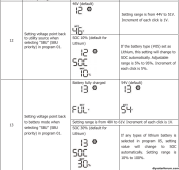
1701468788725.png
Because you've already chosen PYL in your program 5, the programs 12 & 13 should automatically show SOC in percent instead of voltages (if running in "SBU" mode!!

Now this is where I get really interested, but confused at the same time. SolarAssistant does not mention such settings in their info for Axpert Inverters.
  • How do you get data from SolarAssistant? Does it connect via WiFi, or does a cable have to be installed? Or worse, does it only work with a raspberry PI? Judging from the site, Solar Assistant does what WatchPower does, with only one thing added: it will control setting 99 and 100 (timers to switch to grid or solar) by SOC rather than Voltage. Other than that I can not see any difference.
Both Axpert Max and EG4-6500EX (and a lot of others) are built by Voltronic and because of that, they are very similar. Search for Voltronic in the SolarAssistant documentation and it will match our inverters.

SolarAssistant runs ONLY exclusively on a Raspberry Pi - by intention to be a robust 24/7 solar monitoring and controlling solution - more like a device instead of just a "program".

You can use WiFi or Ethernet to connect this SolarAssistant "device" to your home network (I'm using WiFi) and the location of the Raspberry Pi has to be close to your inverters/batteries. The inverters are connected via RS232 to the inverters (via USB-to-RS232/RJ435 adapter cables). Optionally you can connect the batteries via RS485 (via USB-to-RS485/RJ45 adapter cables) or RS232 (via USB-to-RS232/RJ435 adapter cables). It depends on which battery model you're using.
Beside the inverter information, SolarAssistant may get the battery information from the inverters also if the inverters are closed loop connected to your battery BMS (like in your case). If the inverters are not closed loop communicating with the batteries, you can attach the batteries directly to SolarAssistant.
  • What are 'smart home rules' and how do they control the AC-in contactor?
Because SolarAssistant now has all the inverters and battery data, it could (optionally) send these data via MQTT to other systems for further processing (it's not a requirement - SolarAssistant runs by itself and has also some automation possibilities).

But in case you already have a complete SmartHome system like HomeAssistant or OpenHAB (like me) which are able to communicate via MQTT with other systems, you will have all the power of these SmartHome systems also available for SolarAssistant. e.g. monitoring different values, developing rules based on value changes, etc. etc.
Here are some typical rule examples of a SmartHome system:
  • Switch on all lights and sirens if a door or windows contact will be activated (alarm system).
  • Switch on specific lights depending on which motion detectors are activated around the house.
  • Switch on/off lights depending of daylight values (sunset/sunrise).
  • Switch on my garage air conditioner if my inverter temperatures getting too high (I live in the hot Arizona Mohave desert).
  • Switch on my AC-in contactor in case my battery voltage (or SOC) will drop below a specific value.
  • etc.
To be able to do all this stuff, for sure all your sensors and actors must be connected to your smart home system and to do that, they must be kind of "smart". There are some standard protocols to connect smart devices to SmartHome systems (e.g. Z-Wave, ZigBee, MQTT, etc.).

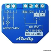
In my case, the inverters are now "smart" via integration with the help of SolarAssistant and MQTT into my OpenHAB system. The Shelly Plus 1 dry contact relay is "smart" because I flashed it with Tasmota to be a MQTT controllable remote WiFi relay and it's also integrated in my OpenHAB (at the end, the Shelly relay drives my typical 110Amp/120VAC contactor to connect the grid to the AC-in).

Now I can develop rules in OpenHAB which will be triggered if my battery voltage changes to specific values and in this rule I can send commands to the Shelly relay which opens or closes the AC-in contactor.

  • Do you have an explanation as to why your Voltage values are so different from mine? (For example, the batteries have been charging all day by the PV panels, the SOC is now @70%, but the voltage is only 50.5V... And thus the grid keeps charging the batteries. As I said, I will probably never get to the minimum of 51V...
I'm not really sure - but as far as I remember the Pylontech batteries only use 15 LFP cells instead of usual 16 to build a whole battery which reduces the battery voltage. So you need to adjust your voltages compared to mine. You need to know the relation of your battery charging voltage chart with it's SOC and also the discharging chart to know very exactly which voltage matches which SOC (it's different for charging and discharging).

  • This I get. How it gets done 'automatically' is probably with SolarAssistent, or SmartHome. (My house runs on a domotics system called SmartHome (by Carlo Gavazzi), but I suppose you are talking about something entirely different). But you cannot do the same in the other 'direction': to achieve that you need a WiFi relay... Correct? (But then how do you make the dry contact switch?) In any case, voltages of 53 and 52 are out of my league. Even 51V seems unatainable. In which case, the grid would NEVER be disconnected again.

    Do you have to do that manually every day? Or can this be achieved "automatically?
I set everything up in a way that it's completely fully automatic.

  • As of here, it is getting really difficult. I get the 0.1V steps. But you seem to run SolarAssistant (on a PI), this then connects to other software called SmartHome. (Never heard of openHAB) And then you need to reset the system manually on a daily basis. But I could achieve it by learning how to program MQTT code (of which I have never heard either)...
The rules are automatically adjust the values of program 12 depending on inverter mode and battery voltage. As I mentioned OpenHAB is like HomeAssistant, just an open SmartHome system.

But all this is not really required to run a solar system, it just gives you a lot more options to control and optimize everything very accurate.
Pffff, I can see why Axpert is so much cheaper than my other 2 Victron systems. All I need to do there is take my phone, open the App and change whatever I want.
I probably (and hopefully) wrongly interpreted or misunderstood quite a few things in your answer. But it seems like a real daunting task to get where I want to be.

PS: fancy a 2 or 3 week holiday in Spain? You are welcome to my house. All yours and free! Albeit that you might run a bit short of electricity. But surely you would be able to manage that...
Thanks for the invitation (y)
In case I would ever be in Spain I will let you know :)

Hope to read you soon.
Greetings, Kurt
 
Because you've already chosen PYL in your program 5, the programs 12 & 13 should automatically show SOC in percent instead of voltages (if running in "SBU" mode!!
Hi Frank,
You are a lucky man. Unfortunately The Max ii instructions do not offer the option for SOC! If they had, my problem would be solved. I only have the top option of program 12 & 13 and not the bottom bit that offers SOC %.

I have little time now and will read the rest of your feedback later. But for now, I wanted to let you know that I do not have the SOC option...

Greets, Kurt
 
But in case you already have a complete SmartHome system like HomeAssistant or OpenHAB (like me) which are able to communicate via MQTT with other systems, you will have all the power of these SmartHome systems also available for SolarAssistant.
Hi Frank,

I now get to understand you better. These are indeed brand names or/and open source applications. We have the same sort of systems here, but other brands and software.
Problem is that the house here already runs on an automated system (Basically Eaton). It is quite dated (2007) and I am planning to update it to to a newer version soon. I doubt however that it will be possible to integrate the Inverter (nor the airco for that matter) because the software is not open source.
So I guess that I am stuffed in that section too.
You need to know the relation of your battery charging voltage chart with it's SOC and also the discharging chart to know very exactly which voltage matches which SOC (it's different for charging and discharging).
I am indeed monitoring it (by looking at by WatchPower every now and then and taking a screenshot). The switch to grid voltage is not so much of a problem (I could set that to either 48 or47V), it is the return to the batteries which is difficult. Program 13 does not allow a lower voltage than 51, Which is very high up. In my case 49V would be acceptable, but the system does not allow it. Yesterday I reached 51V @70%, but I believe that it depends on the intensity of charge: when charging on high amperage the Voltage goes up, but later in the day I was still charging with the battery 99% full, but Voltage only @50.3.
And here lies the problem.

I do have an old Strawberry PI lying about somewhere, and I could give it a try, But if I understand you and your system correctly, then I do not think that connecting SolarAssistant will help me at all. Is this a correct assumption?

In which case I would be back at square one... How to finetune program 12 and 13?

Looking forward to your reply.
Kurt
 
Hi Frank,

I now get to understand you better. These are indeed brand names or/and open source applications. We have the same sort of systems here, but other brands and software.
Problem is that the house here already runs on an automated system (Basically Eaton). It is quite dated (2007) and I am planning to update it to to a newer version soon. I doubt however that it will be possible to integrate the Inverter (nor the airco for that matter) because the software is not open source.
So I guess that I am stuffed in that section too.

I am indeed monitoring it (by looking at by WatchPower every now and then and taking a screenshot). The switch to grid voltage is not so much of a problem (I could set that to either 48 or47V), it is the return to the batteries which is difficult. Program 13 does not allow a lower voltage than 51, Which is very high up. In my case 49V would be acceptable, but the system does not allow it. Yesterday I reached 51V @70%, but I believe that it depends on the intensity of charge: when charging on high amperage the Voltage goes up, but later in the day I was still charging with the battery 99% full, but Voltage only @50.3.
And here lies the problem.

I do have an old Strawberry PI lying about somewhere, and I could give it a try, But if I understand you and your system correctly, then I do not think that connecting SolarAssistant will help me at all. Is this a correct assumption?

In which case I would be back at square one... How to finetune program 12 and 13?
Because your inverter does not support SOC percent unit for setting 13 and the lowest value in voltage unit is 51V which is too high for your 15-cell Pylontech, you can't optimize program 13 to disconnect "earlier" from the grid. For this scenario the only solution which I see is an external disconnect contactor (relay) between the AC-in and the grid.

This contactor should disconnect the inverter from the grid at a configurable voltage (in your case something between 49.5V and 50.5V as I understand it correctly). The inverters don't have a problem if they are running in "Grid" mode and charging the batteries (and bypassing at the same time) and you suddenly disconnect the grid from the AC-in. There will be no outage at the moment, when you disconnect the grid and the inverters will run on batteries (you can try this by manually switch of your AC-in breaker while the inverters are still in "Grid" mode and charging).

There are different possibilities to achieve such an external AC-in contactor automatic.
  • Without a SmartHome integration, you need to build a circuit which measures your battery voltage and disconnect the (high Amp) AC-contactor/relay from the AC-in if the battery voltage jumps over your selected trigger voltage. On the other side the contactor must be connected to the grid before the battery voltage drops below the voltage which is set in program 12.
  • With SmartHome integration you are able to get all inverter and battery parameters (via SolarAssistand and transferred via MQTT to e.g. HomeAssistant or OpenHAB). For sure, for this solution you also need some "hardware". The AC-in contactor/relay must be implemented and it must be remotely controllable but the measurement of the battery voltage and the logic to set the trigger voltages could be done in software and this is way more flexible. But if you don't already have such a SmartHome it takes time to set such a system up in a reliable way and you need to understand it. If you anyway have plans to do install a SmartHome system (which is able to get data via MQTT), it's the perfect solution.
Just leave the setting in program 13 to what (too high) value ever and control the AC-in disconnect "external".

I don't know how good you are in electric/electronic, but to build such a remote AC-in contactor this would be a way to achieve it with standard components which are not so expensive.

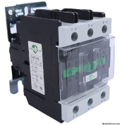
  1. First you need to select the right AC contactor which fits your local voltage requirements and the amperage needs to be at least what your inverter(s) maximum draw from the grid. In case for typical european 230V system you need a contactor which is able to switch 230VAC with the amperage which is used for your AC-in breaker (in case you would have 3 inverters in typical european 3-phase system, you would need a 3-pole contactor, one pole for each phase). The contactors need to have the typical N)/NC/COM switching terminals. You also need to select the coil voltage to control the contactor

    (In my case, US 240V/120V split phase system, I've chosen 110Amp / 120ACV contactors with 2-poles - because of the two phases in split phase setup I need at least 2 inverters with 2 AC-in's - in fact I use two 3-pole contactors, because I'm running 6 inverters in parallel - 3 for phase1 and 3 for phase2).

  2. Second you need to select a remote dry contact relay to drive the coil of the AC contactor (you'll not be able to find a cheap all-in-one AC contactor which is remote controllable, that's the reason why I have chosen this 2 step relay solution). I've chosen the Shelly Plus 1 because I was already familiar with this type and know how to integrate this into my existing OpenHAB. (side note: I don't like to depend on cloud solutions, so I re-flash all my Shelly relays with Tasmota firmware to be just a local WiFi device which can be controlled via MQTT and not longer via the cloud based Shelly app). But the model of the remote relay does not matter as soon as you can control it remote with your SmartHome solution and has enough switching specification in Volts and Amps to drive your AC-in contactor coil and it's a real dry contact version!
To give you an idea how these looks like...

I use 2 of these for my 6 inverters with 2 phases: An this is the remote relay:
(e.g. https://www.amazon.com/gp/product/B09F5Z9D2H) (e.g. https://www.amazon.com/gp/product/B09X27Y5XL)

1701622930562.png 1701623071865.png
Looking forward to your reply.
Kurt
 
I have taken a couple of days to roam the net and see if any other solution would pop up somewhere, but so far... nothing.

What I will do to "sort of" make it work is go low tech and just add a timer to the grid relay. In that case I can limit the time for the grid to fill in the missing power. It is mostly in the morning that I run the risk of running out of power. 47V is low, but at least it will make the grid kick in. I allow the grid to charge at max 50A, which is a reasonable speed, but still limits the amount of power which I take from the grid. I allow to charge until 08 in the morning, after which the timer will cut off the relay.
Once past 8 the PV panels take over... By the end of the day I should reach 51V, which makes the dry contact to disengage from the grid. It will kick in again after midnight IF the batteries go under 47V.

That keeps the grid in the lower price range (cheapest price per kW used and cheapest rate to "reserve 5kW).

In the mean time I can only hope that one day there will be a firmware update that will provide a toggle between 10 and 30% like you have Frank.

Thank you again for all the trouble you took to help me out.
Greets, Kurt
 
Back
Top