diy solar

diy solar

Basic Question About Current in DC System

chadmichael

New Member
Joined
Feb 26, 2022
Messages
52
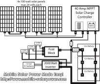
Assuming the schematic below, the "Classic 400 Watt" system on this web site, and assuming that I udnerstand DC electrical system correctly in that current can only flow in one direction on the circuit, how can the charge controller charge the batteries when anything at all is pulling a load from the batter? It seems to require that current be flowing out the main positive from the battery to, say, the inverter or fuse block, while current is flowing into the batteries from the charge controller at the same time? Isn't this current flowing in two directions on the same positive wire?

How does this work? What am I missing?


1653279458649.png
 
The charge controller will power the loads before it charges the battery. If the charge controller is providing more power than that needed by the loads then the excess power will go toward charging the batteries. If the charge controller is providing less power than that needed by the loads then all of the charge controller power will go to the loads and power from the battery will be used to make up the balance.
 
Current is flowing in one direction but it gets split into 2 paths. You got 40 amps available from charge controller. It will attempt to get all that current to flow by raising voltage. Your battery will absorb all of this current at certain voltage. Connect 15A of loads in parallel with the battery and 25A is now flowing into the battery. Charge controller still sees 40A load but battery receives 25A because loads consume 15A.
 
You got 40 amps available from charge controller.
You got up to 40A available. Depends on the amount of solar panels, the current solar conditions, the current loads, and the current battery condition.

It will attempt to get all that current to flow by raising voltage.
The MPPT SCC will output the battery charge voltage. The actual current will be adjusted based on all of the above factors, limited to a max of 40A for this specific SCC.
 
The charge controller will power the loads before it charges the battery.
Per Clemj https://en.wikipedia.org/wiki/Kirchhoff's_circuit_laws that current flow is decided on by the resistance in the circuit of the various loads. (the inverter,the battery,the 12v appliances)

In OP attached schematic its typical to also buss the neg as opposed to the config shown (SCC directly to battery neg)
 
Thanks everybody. I learned something and it makes sense!

My next question is about the wire running between the larger 100-250A fuse and the charge controller. That wire is sized for the 40 Amps that the charge controller could push, which I understand fine. But it's hard for me to know whether that small wire connecting the larger fuse to the smaller fuse on the path to the charge controller needs to be 8 AWG (sized for the charge controller's 40Amps) OR whether it needs to be the large wire size of the main path to the inverter?
 
But it's hard for me to know whether that small wire connecting the larger fuse to the smaller fuse on the path to the charge controller needs to be 8 AWG (sized for the charge controller's 40Amps) OR whether it needs to be the large wire size of the main path to the inverter?
The wire on both ends of the 50A SCC fuse can be sized for the 40A load (8AWG).

Using a bus bar makes this a lot simpler and clearer. I don't know why Will doesn't use bus bars on these schematics but it really helps. It avoids confusion and avoids all of the multiple connections on a single fuse. Use both positive and negative bus bars.
Im using a bus bar to join my batteries, and it will yield two connection points. I'll have three connections: charge controller, inverter and fuse block. I assume I can wire these each independently, with a fuse per wire. It's not a problem to attache two wires of different sizes to the same bus bar connection is it? They would each then have their own appropriately sized fuse.
 
It's not a problem to attache two wires of different sizes to the same bus bar connection is it?
Two wires on one stud is fine. Just be sure to put the bigger wire with the higher amp load on first against the bus bar. The smaller wire can go on top of the larger wire.
 
Back
Top