simjoc
New Member
- Joined
- Aug 23, 2020
- Messages
- 12
Hello,
Upon request, I will describe my experience with Batrium along with Victron VenusOS.
I'm using the Batrium BMS for years at my home system and it never lets me down so I decided to use it also in my camper.
What I used:
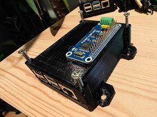
To start, I attached everything and began the installation of VenusOS from Victron. Following the guide, it was a quick process: [https://github.com/victronenergy/venus/wiki/raspberrypi-install-venus-image]
Once the installation was complete, I had to convert the installation to the Large variant, see [https://www.victronenergy.com/live/venus-os:large].
This might not be necessary, but it provides additional features like Node-red, etc. I also installed GuiMods to have a nice interface, but skipped veCanSetup as it turned out to be unnecessary.
After installing and updating everything, I rebooted the Raspberry; this is crucial, or else the Waveshare won't be detected.
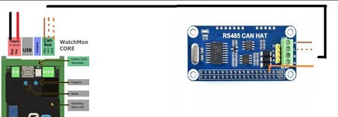
Then, I went to Settings >> Services, where I found can0. This caused me some trouble, but I had forgotten to restart the Raspberry. I think that was the issue. Now, VenusOS has communication with Waveshare, and we can connect both. I connected the following wires, and the wire color is arbitrary.
Next, in VenusOS, under Settings >> Services >> can0, I set the profile to CAN-bus BMS (500 kbit/s). Immediately, I saw a connection, and Batrium was in contact with VenusOS. TX and RX, all packets were received.
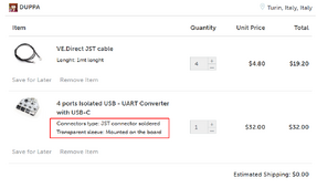
Now, it was time to connect my three Victrons MPPT 75/10. I have three solar panels of 140wp, each with its own connection and MPTT. I initially used cheap UART USB plugs, but they caused a lot of problems. Then, I ordered the following isolated USB-UART converter with cables: [https://www.tindie.com/products/saimon/4-ports-isolated-usb-uart-converter-with-usb-c/] It works fantastically, thanks to DUPPA!
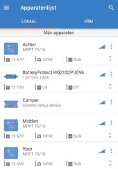
Now, I could make VenusOS communicate with all three MPTTs, and it worked well. After all updates, I turned off Bluetooth and tested the communication between Batrium and VenusOS. I grabbed an ice cream and held the (external) temperature sensor of Batrium against it for a while. When the temperature dropped below 10 degrees, you could see all MPTTs immediately stop charging, perfect! The next step was to connect the Victron Multiplus Compact 12/2000, but that was done quickly. A Victron MK-3 USB (VE.Bus to USB) in the USB port of the Raspberry, a restart, and the Multiplus appeared in the menu right away.
The last step was to connect the tank sensor. I use pressure sensors connected at the bottom of my tank, currently only in the freshwater tank. It was a matter of connecting the Victron GX Tank 140 with the USB port, and the four sensors were immediately found. First, calculate the zero point with an empty tank, then calculate the when the tank is full. Unfortunately, I don't have screenshots, but the whole setup is very neat and clear.
All of this worked fantastically for a few months; however, I might have damaged my batteries. But that's is a different topic.
I hope this helps others! For questions shoot :D
Edit1: I don't have screenshots of it but all the information from batrium cellinfo / temperature / shunt was visible in the VenusOS
Edit2: Thanks to the Batrium crew for the help with setting up the system
Upon request, I will describe my experience with Batrium along with Victron VenusOS.
I'm using the Batrium BMS for years at my home system and it never lets me down so I decided to use it also in my camper.
What I used:
- Raspberry Pi 4
- Passive heatsink for Raspberry (Pimoroni EAN: 0606034879669) €15
- 3D print to mount the Raspberry (https://www.thingiverse.com/thing:5250782)
- Waveshare RS485 CAN HAT (ASIN: B09JKJCMHN) €19
- A good and reliable SD card

To start, I attached everything and began the installation of VenusOS from Victron. Following the guide, it was a quick process: [https://github.com/victronenergy/venus/wiki/raspberrypi-install-venus-image]
Once the installation was complete, I had to convert the installation to the Large variant, see [https://www.victronenergy.com/live/venus-os:large].
This might not be necessary, but it provides additional features like Node-red, etc. I also installed GuiMods to have a nice interface, but skipped veCanSetup as it turned out to be unnecessary.
After installing and updating everything, I rebooted the Raspberry; this is crucial, or else the Waveshare won't be detected.
Then, I went to Settings >> Services, where I found can0. This caused me some trouble, but I had forgotten to restart the Raspberry. I think that was the issue. Now, VenusOS has communication with Waveshare, and we can connect both. I connected the following wires, and the wire color is arbitrary.

Next, in VenusOS, under Settings >> Services >> can0, I set the profile to CAN-bus BMS (500 kbit/s). Immediately, I saw a connection, and Batrium was in contact with VenusOS. TX and RX, all packets were received.
Now, it was time to connect my three Victrons MPPT 75/10. I have three solar panels of 140wp, each with its own connection and MPTT. I initially used cheap UART USB plugs, but they caused a lot of problems. Then, I ordered the following isolated USB-UART converter with cables: [https://www.tindie.com/products/saimon/4-ports-isolated-usb-uart-converter-with-usb-c/] It works fantastically, thanks to DUPPA!

Now, I could make VenusOS communicate with all three MPTTs, and it worked well. After all updates, I turned off Bluetooth and tested the communication between Batrium and VenusOS. I grabbed an ice cream and held the (external) temperature sensor of Batrium against it for a while. When the temperature dropped below 10 degrees, you could see all MPTTs immediately stop charging, perfect! The next step was to connect the Victron Multiplus Compact 12/2000, but that was done quickly. A Victron MK-3 USB (VE.Bus to USB) in the USB port of the Raspberry, a restart, and the Multiplus appeared in the menu right away.
The last step was to connect the tank sensor. I use pressure sensors connected at the bottom of my tank, currently only in the freshwater tank. It was a matter of connecting the Victron GX Tank 140 with the USB port, and the four sensors were immediately found. First, calculate the zero point with an empty tank, then calculate the when the tank is full. Unfortunately, I don't have screenshots, but the whole setup is very neat and clear.
All of this worked fantastically for a few months; however, I might have damaged my batteries. But that's is a different topic.
I hope this helps others! For questions shoot :D
Edit1: I don't have screenshots of it but all the information from batrium cellinfo / temperature / shunt was visible in the VenusOS
Edit2: Thanks to the Batrium crew for the help with setting up the system
Last edited:


