diy solar

diy solar

Battery Charge Speed

I'm a bit confused. If you have a 48v system with a maximum battery charge rate of 58v

Rate would be analogous to current. 58V is presumably the absorption voltage.

but currently set to a limit of 56v, and the battery cells are at a state of charge of say 50v, for example, and you are charging at maximum voltage and amperage, what would you expect the voltage to read at the battery terminals?

Let me state it another way:

If equipment is measuring 56V @ 124A, but the BMS is reporting 50V, you have system resistance equivalent to 900-something feet of 4/0 cable.

OR, the BMS is just flat out wrong.

Under normal circumstances in a proper installation, the voltage induced by the current (the voltage measured by the chargers) would be very close to the voltage measured independent of current (shunt, BMS).
 
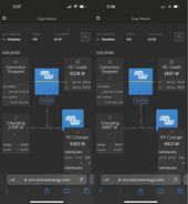
Hello, I don't think the DVCC is active because the maximum charge voltage is set to 54, but right now the batteries are charging up to 56, which is what the installer currently has set. I don't recall where he has the 56v limit set. At one point we had 58v set as the limit, that is when we got up to a 7,192w charge rate

View attachment 222269

The GX can only impose these limits on GX connected devices. Chargers not properly connected to the GX device operate according to their own settings.
 
I have two weird things going on. One is that the battery terminal voltage reaches the max set limit, 56v in this case, as soon as I get the charge current up to 124amps. The second is that the charge current doesn't go above 124 amps.

You actually have ONE thing going on as the two values are related. The voltage is what's limiting the current.
 
I hear you and I'm not knowledgeable enough to say differently, but if you look at the charge curve, the voltages reported by the BMS seem to be about right for the SOC.

I'm a bit confused. If I have 56v set as the charge voltage limit, and the SOC is currently at 30%, for example, what voltage would you expect to read at the charger controllers, battery terminals, and internal battery cells assuming I'm charging at maximum charge rate?

View attachment 222290View attachment 222291

This battery looks weird. Based on the dis/charge curves, and the max charge voltage, I suspect this is a 15S battery.
 
ESM-48100B1 everything I have seen says Telecom.
Every time I see telecom like in the DC generator I have it’s max charging is 53.5 VDC.

No idea if it means anything but could be 15s.

Nothing I have seen specifically says that..but.
 
This is a 15S battery with voltage boost function intended to be paralleled with lead acid battery.

It is capable of CAN communications, but it doesn't appear to be compatible with Victron based on Victron forum posts.

IMHO, while I initially suspected the wiring, and I'm not confident that it's as robust as it should be for the installation, I am now suspicious that this "boost" function is providing an external "fake" voltage that will thwart attempts to charge it at a higher rate because it's making the chargers THINK they are hitting a higher voltage.

In my opinion, these batteries are a very poor choice due to their 15S configuration, their BMS imposed limited charge capability, and their odd behavior. They have features for specific applications that are not desirable for a simple (or complex) off-grid power system.

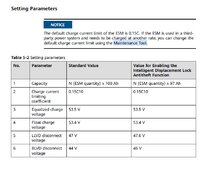
Per this:


I suspect the BMS are forcing a ~120A limit due to the charging limit of 0.15C10 - or 15A/battery.

It does make some comment about being able to change this using the "maintenance tool" for these batteries - this may enable you to charge at higher current. Your installer or whoever sourced the battery should have a clue about this.

ALL chargers (Both Quattro, all MPPT) must be individually configured for:

56.4V absorption
54.5V float

DVCC can be used to restrict the charge voltage to something lower. Higher will be ignored.

Recommend set DVCC to 120A so the system is in agreement with the BMS limit.

The arrogant prick was ultimately wrong, but I'm pretty sure he got to the bottom of it. :p
 
Last edited:
Looping back to the original post:

1) When I'm charging at the faster we can achieve now (7,192), Victron will report the voltage at 58v, and when hooking up a volt meter to any of the batteries, I get 58v, so Victron is reporting the voltage correctly. However, the BMS says the batteries are at a lower voltage because they are not full, say 50.0v for example. Is this the way it is supposed to work, ie the faster the batteries are getting charged, the higher the voltage is reported, regardless of the voltage level (state of charge) of the batteries? If this is how it supposed to work, then maybe I don't have a problem and 7,192w is the fastest I can charge these batteries?

This is the result of your odd battery's "boost" function feeding the system a fake high voltage in order to restrict charging.

2) If the 7,192w is not supposed to be my limit, then how I do I increase the limit?

Reprogram the batteries to accept more than 0.15C (120A) per the "maintenance tool".

3) Related question to number 2. The fastest charge I can get is 58v and 124 amps. Do both of these values make sense as the limits that I have been getting, or should one, or both, of them be higher?

Unfortunately, this is not a normal situation. In how this battery operates, it makes sense, but with normal batteries, it doesn't.
 
I believe this proves the BMS is limiting to 120A:

1718496135862.png

When only 55A was being delivered, battery reported true voltage.

Yet, one minute earlier, when ~120A was delivered the BMS forced voltage to 56V to limit charge current to 0.15C.

I am not concerned about 120A vs. 123.20A or 124A. It's very common for these to be inexact. Even with DVCC controlling the limits, I've seen discrepancies of the same magnitude, but they tend to be conservative. The +3.2A likely results from cumulative errors in the 8 batteries' voltage and current measurements.
 
Looping back to the original post:


This is the result of your odd battery's "boost" function feeding the system a fake high voltage in order to restrict charging.


Reprogram the batteries to accept more than 0.15C (120A) per the "maintenance tool".


Unfortunately, this is not a normal situation. In how this battery operates, it makes sense, but with normal batteries, it doesn't.


Maybe this is why there are different charge specs on different websites depending on what you look at they are quite difference.

It might also explain what looks to be undersized wiring. The designer of the system knew of these limitations and use a wire size appropriate to the max capacity of the batteries in default configurations.

Might be worth verifying that wiring and fuses before increasing current through them.
 
Maybe this is why there are different charge specs on different websites depending on what you look at they are quite difference.

The boost feature is specific to the B1 model. It appears to be acceptable to also set voltages appropriate for 15S.

It might also explain what looks to be undersized wiring. The designer of the system knew of these limitations and use a wire size appropriate to the max capacity of the batteries in default configurations.

I can't agree with this as you don't size wires purely for charge current. You size for max current, whichever direction. With 20kVA of discharge, they need to handle about 500A. They can definitely discharge more than 15A ea.

Might be worth verifying that wiring and fuses before increasing current through them.

10,000%
 
I can't agree with this as you don't size wires purely for charge current. You size for max current, whichever direction. With 20kVA of discharge, they need to handle about 500A. They can definitely discharge more than 15A ea.

Of course you are right, the wires _should_ be sized to the inverter/highest possible current through them with a safety margin.
 
Interesting culprit here (battery with internal boost mechanism). I would never have guessed.

In any case, if you get the battery to accept more charge, be careful with the wiring since while they may handle the current current (no pun intended), they may be undersized for more.
 
Looping back to the original post:


This is the result of your odd battery's "boost" function feeding the system a fake high voltage in order to restrict charging.


Reprogram the batteries to accept more than 0.15C (120A) per the "maintenance tool".


Unfortunately, this is not a normal situation. In how this battery operates, it makes sense, but with normal batteries, it doesn't.
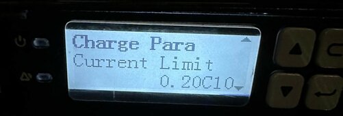
I checked the current limit set in the BMS device have below the right rack. It says the current limit is .20C10 ( image below). Next, the current limit shown on the datasheet I included in other comments in this thread showing a normal rating of .2C (first page and also in title of charge curve). I can't dispute the math that 15x8 = 120, and I'm rooting for this to be the issue as I'm hoping increasing the current limit is simple and will immediately increase my charge limit. 1) Other than that math, what did you find in the literature to suggest the current limit is 15amps and not 20amps?

Next, I'm 90% sure I understand that you are saying the voltage, when charging, should be very similar at the charger controllers, battery terminals, and reported by the BMS. To help put the nail in the coffin for my understanding, I would like to propose a hypothetical example and get your confirmation please. Looking at the charge curve on page 2 of the datasheet, if I'm at 100 mins of charge time (.2C, 35 Celsius), the charge voltage should be 50v. 2) Therefore, regardless of what current the batteries are getting charged at, the voltage measured at the charge controllers and battery terminals should be close to 50v?

3) If I have the installer increase my wire sizing to the recommended sizing, what charge current limit do you recommend, and why, for my system? It is a little confusing for me that the batteries report 58v and 100amps as the maximum charge parameters, but then the default is 15, or 20. That said, I'm assuming for the life of the battery, it is better to consistently charge at lower rates even if the maximum is significantly higher. I understand that. My plan would be to leave the charge current at a lower amount, 15-20 amps per battery, for most days of the year, but sometimes I will want the option to charge faster. I run two houses (2 electric ovens, 2 water heaters, 2 fridges, 2 washers, 2 dryers, 2 dishwashers), pool pump, hot tub pump all from this system, and the 2nd house is a full time Airbnb. Sometimes it will be worth it to me to reduce the life of the batteries in exchange for happy guests and family. While of course I want the system to last a good amount of years, I'm off grid and my primary objective is for the system to supply power and satisfy our needs/wants. I make the same conscious choices with our Tesla in the states, there are times I have run it down to 2% charge and times I supercharge it consistently up to 90-100%. My battery is degraded because of this, but the vehicle serves it purposes, and for me I prefer the benefits enough to justify the degradation.

Next steps: I have asked the installer if he knows of the BMS current limit sets each batteries limit, and either way, what is the current limit for each battery (is it 15amp or 20amp). If he thinks the BMS current limit doesn't override the battery limit, and the batteries are currently limited to 15amps, then I will work with him to raise the current limit of each battery. If that successfully increases the charging current, then we will have finally solved this issue (after 13 months of living with this system, numerous attempts by the installer to fix it, numerous attempts by the supplier, attempt by an installer in Colorado trying to solve it through a video call and accessing my system remotely), and my researching it as much as I can. Don't worry, I haven't forgot about the wires be undersized, I will get the wires replaced with larger wires soon.


BMS current limit.jpg
 
I checked the current limit set in the BMS device have below the right rack. It says the current limit is .20C10 ( image below). Next, the current limit shown on the datasheet I included in other comments in this thread showing a normal rating of .2C (first page and also in title of charge curve). I can't dispute the math that 15x8 = 120, and I'm rooting for this to be the issue as I'm hoping increasing the current limit is simple and will immediately increase my charge limit. 1) Other than that math, what did you find in the literature to suggest the current limit is 15amps and not 20amps?

The link I provided was to a huawei forum. The information was linked by a moderator to that forum.


Next, I'm 90% sure I understand that you are saying the voltage, when charging, should be very similar at the charger controllers, battery terminals, and reported by the BMS.

Mostly true, but there's a twist.

Chargers direct measured voltages will always be higher, but it should be a small delta unless wire/connection resistance is too high. With DVCC/SVS enabled, the Lynx shunt is passing it's voltage measurement to all GX connected chargers, so losses through their wiring are not considered.

In your case, the shunt voltage is the "master" for all victron hardware. Since the shunt is not measuring a voltage influence by current, it SHOULD measure nearly exactly the same as the BMS.

It took me a minute to realize that the voltage difference was actually INSIDE the battery.

So, to summarize, with DVCC enabled and SVS enabled the shunt voltage should be nearly identical to the BMS voltage as the shunt is measuring the true voltage at the battery terminals and passing it to all Victron chargers. Any difference between BMS and shunt is either simply error, slight resistance issues or the BMS boost function.

To help put the nail in the coffin for my understanding, I would like to propose a hypothetical example and get your confirmation please. Looking at the charge curve on page 2 of the datasheet, if I'm at 100 mins of charge time (.2C, 35 Celsius), the charge voltage should be 50v. 2) Therefore, regardless of what current the batteries are getting charged at, the voltage measured at the charge controllers and battery terminals should be close to 50v?

100 minutes of charge time is measured from a completely empty battery. If you start at 20% charge, you would start at roughly the 60 minute mark, and your 100 minutes of charging would correspond to a voltage value at the 160 minute mark.

You had it mostly right until the last sentence. When you said "regardless of current" - that is incorrect. Those curves are specifically for 20A charges from 0% SoC. More current means higher voltage and less current means lower voltage at any given time as measured from 0%.

Lastly, curves are guidelines. They won't correlate 100% to reality.

3) If I have the installer increase my wire sizing to the recommended sizing, what charge current limit do you recommend, and why, for my system? It is a little confusing for me that the batteries report 58v and 100amps as the maximum charge parameters, but then the default is 15, or 20. That said, I'm assuming for the life of the battery, it is better to consistently charge at lower rates even if the maximum is significantly higher. I understand that. My plan would be to leave the charge current at a lower amount, 15-20 amps per battery, for most days of the year, but sometimes I will want the option to charge faster. I run two houses (2 electric ovens, 2 water heaters, 2 fridges, 2 washers, 2 dryers, 2 dishwashers), pool pump, hot tub pump all from this system, and the 2nd house is a full time Airbnb. Sometimes it will be worth it to me to reduce the life of the batteries in exchange for happy guests and family. While of course I want the system to last a good amount of years, I'm off grid and my primary objective is for the system to supply power and satisfy our needs/wants. I make the same conscious choices with our Tesla in the states, there are times I have run it down to 2% charge and times I supercharge it consistently up to 90-100%. My battery is degraded because of this, but the vehicle serves it purposes, and for me I prefer the benefits enough to justify the degradation.

First, I would size the wires exactly per the Victron manual recommendations. Between the lynx and the inverters EACH needs 2X 1/0 cables OR 1X 4/0 cable. Period. Based on 60A, the MPPT need at least 4awg.

Between the batteries and the lynx, the cables need to be sized according to the anticipated current. If you had each battery individually connected to the lynx (and you'd need more power-ins), 2awg would likely be fine, BUT since some are paralleled before connecting to the lynx, it depends.

A competent electrician should be able to size wires in their sleep, on ambien, while sleeping off a wicked night of binge drinking.


Next steps: I have asked the installer if he knows of the BMS current limit sets each batteries limit, and either way, what is the current limit for each battery (is it 15amp or 20amp). If he thinks the BMS current limit doesn't override the battery limit, and the batteries are currently limited to 15amps, then I will work with him to raise the current limit of each battery. If that successfully increases the charging current, then we will have finally solved this issue (after 13 months of living with this system, numerous attempts by the installer to fix it, numerous attempts by the supplier, attempt by an installer in Colorado trying to solve it through a video call and accessing my system remotely), and my researching it as much as I can. Don't worry, I haven't forgot about the wires be undersized, I will get the wires replaced with larger wires soon.

Similar to what you propose, here is how I would proceed:

First: Program BMS for 0.5C. This likely needs to be done individually on each battery. I suspect that if a single battery is at a lower value, that will force all of them to the lower value. If they are connected to some kind of management hub that passes settings to all, you may not need to do them individually. I chose 0.5C to try and eliminate the battery from engaging the boost function.

Second: Set DVCC for 53.25V and 120A charge current.

Since this is a 15S battery, the chargers being set to > 54V may further encourage triggering the voltage boost function and tapering current. 53.25 is 3.55V/cell, which is more than adequate for fast charges in most cases.

I also suspect that the batteries may have an SoC based taper as well, e.g., when charging at 50% SoC, there will be no restrictions, but as cell voltages rise and SoC increases, the rules for voltage boosting may become more "protective".

I would then experiment by raising current first and then voltage (up to 54V) to see if you can gain higher current charging.
 
The link I provided was to a huawei forum. The information was linked by a moderator to that forum.


Mostly true, but there's a twist.

Chargers direct measured voltages will always be higher, but it should be a small delta unless wire/connection resistance is too high. With DVCC/SVS enabled, the Lynx shunt is passing it's voltage measurement to all GX connected chargers, so losses through their wiring are not considered.

In your case, the shunt voltage is the "master" for all victron hardware. Since the shunt is not measuring a voltage influence by current, it SHOULD measure nearly exactly the same as the BMS.

It took me a minute to realize that the voltage difference was actually INSIDE the battery.

So, to summarize, with DVCC enabled and SVS enabled the shunt voltage should be nearly identical to the BMS voltage as the shunt is measuring the true voltage at the battery terminals and passing it to all Victron chargers. Any difference between BMS and shunt is either simply error, slight resistance issues or the BMS boost function.


100 minutes of charge time is measured from a completely empty battery. If you start at 20% charge, you would start at roughly the 60 minute mark, and your 100 minutes of charging would correspond to a voltage value at the 160 minute mark.

You had it mostly right until the last sentence. When you said "regardless of current" - that is incorrect. Those curves are specifically for 20A charges from 0% SoC. More current means higher voltage and less current means lower voltage at any given time as measured from 0%.

Lastly, curves are guidelines. They won't correlate 100% to reality.


First, I would size the wires exactly per the Victron manual recommendations. Between the lynx and the inverters EACH needs 2X 1/0 cables OR 1X 4/0 cable. Period. Based on 60A, the MPPT need at least 4awg.

Between the batteries and the lynx, the cables need to be sized according to the anticipated current. If you had each battery individually connected to the lynx (and you'd need more power-ins), 2awg would likely be fine, BUT since some are paralleled before connecting to the lynx, it depends.

A competent electrician should be able to size wires in their sleep, on ambien, while sleeping off a wicked night of binge drinking.


Similar to what you propose, here is how I would proceed:

First: Program BMS for 0.5C. This likely needs to be done individually on each battery. I suspect that if a single battery is at a lower value, that will force all of them to the lower value. If they are connected to some kind of management hub that passes settings to all, you may not need to do them individually. I chose 0.5C to try and eliminate the battery from engaging the boost function.

Second: Set DVCC for 53.25V and 120A charge current.

Since this is a 15S battery, the chargers being set to > 54V may further encourage triggering the voltage boost function and tapering current. 53.25 is 3.55V/cell, which is more than adequate for fast charges in most cases.

I also suspect that the batteries may have an SoC based taper as well, e.g., when charging at 50% SoC, there will be no restrictions, but as cell voltages rise and SoC increases, the rules for voltage boosting may become more "protective".

I would then experiment by raising current first and then voltage (up to 54V) to see if you can gain higher current charging.
Okay, thank you for the detailed answers.

For a follow-up to question 2) I understand that the curve may be different then shown on the spec sheet for different currents, etc., and also different if I don't start at 0. Either way, what I'm really try to confirm is that if the battery cells are at 50.0v (as reported by the BMS), then the battery terminals and charge controllers should also read close to 50.0v when charging and regardless of charge rate?

3) Follow-up. Why do you think it makes sense to initially set 120A on the charge current in the DVCC if I'm trying to get above 120A for the charge current?

New information as of today:
1) I lowered the DVCC max current to 120amp. This brought the voltage down at the battery terminals, charge controllers, and as reported by the shunt down to with-in 1v of the voltage of the cells reported by the BMS. This does seem to support the theory that the boost voltage thing happens when more current is trying to be sent to the batteries

2) I increased the BMS current limit to .25C. Nothing changed, which suggests that the current limit on each battery is at .15C. Funny side note on this. The generator stopped running with-in 10 seconds of me increasing the BMS charge current, which I didn't think was coincidental. Well, it was coincidental, the tank happen to run out of propane right at that time. Switched over to reserve tank and good to go...

3) The installer talked to the supplier about how to access the current settings of each battery, but they were not helpful, and the installer doesn't know how to do it. He contacted someone from India that he thinks maybe able to help. A little bit funny to have to jump through hoops to try and modify settings for a battery they installed, but whatever it takes. This is my first solar system, I will have more influence on the specific components on the next one. Side note, the installer is a great guy and while it isn't great to be dealing with these issues, it is nice to work with good people.
 
Okay, thank you for the detailed answers.

For a follow-up to question 2) I understand that the curve may be different then shown on the spec sheet for different currents, etc., and also different if I don't start at 0. Either way, what I'm really try to confirm is that if the battery cells are at 50.0v (as reported by the BMS), then the battery terminals and charge controllers should also read close to 50.0v when charging and regardless of charge rate?

Yes. If boost function is not active, BMS, shunt and voltmeter at the battery terminals should read very nearly the same value even when charging (or discharging).

3) Follow-up. Why do you think it makes sense to initially set 120A on the charge current in the DVCC if I'm trying to get above 120A for the charge current?

I like to start at established limits. You know the system works safely at this level. I personally prefer to "sneak up" on limits rather than risk exceeding them.

New information as of today:
1) I lowered the DVCC max current to 120amp. This brought the voltage down at the battery terminals, charge controllers, and as reported by the shunt down to with-in 1v of the voltage of the cells reported by the BMS. This does seem to support the theory that the boost voltage thing happens when more current is trying to be sent to the batteries

Good to hear.

2) I increased the BMS current limit to .25C. Nothing changed, which suggests that the current limit on each battery is at .15C. Funny side note on this. The generator stopped running with-in 10 seconds of me increasing the BMS charge current, which I didn't think was coincidental. Well, it was coincidental, the tank happen to run out of propane right at that time. Switched over to reserve tank and good to go...

Glad to hear it was pure coincidence. If you don't solve those quickly, they can make you chase your tail.

3) The installer talked to the supplier about how to access the current settings of each battery, but they were not helpful, and the installer doesn't know how to do it. He contacted someone from India that he thinks maybe able to help. A little bit funny to have to jump through hoops to try and modify settings for a battery they installed, but whatever it takes. This is my first solar system, I will have more influence on the specific components on the next one. Side note, the installer is a great guy and while it isn't great to be dealing with these issues, it is nice to work with good people.

There does appear to be some sort of hub in the picture. Perhaps it works like DVCC in that if the batteries are at a higher limit, the hub can impose lower limits, but it can't force batteries to higher limits.

Some VRM recommendations:

From Device List > Settings > VRM online portal > Log interval - set to 1 min.

A more frequent log interval is useful in troubleshooting. Default is 15 min.

On the advanced tab, you can plot Lynx Shunt "battery voltage and current". This would show the abrupt changes in voltage that would have steered suspicion away from connections to some other influence. Showing 50V and 55A one minute and then 56V and 123A the next would have been a serious WTF? moment.

I'm not the hugest fan, but if you're looking at doing more installations of this nature with Victron equipment OUTSIDE the U.S., Pylontech brand batteries seem to have decent availability outside the U.S. These are also 15S batteries, BUT they are 100% compatible with the Victron ecosystem and will interface with and control the GX device, i.e., you would have been able to charge at something closer to 400A without restrictions with 8 pylontech batteries.

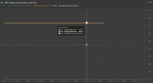
As an example, this is what 2X 304Ah Trophy server rack batteries communicate to the GX device:

1718570766412.png

The system will charge at up to 363.6A up to 56.3V and then naturally tapering the current held at 56.3V. As the SoC/cell voltage increases, it will lower the current limit to slow the charge as it approaches full.

This is also a dual Quattro 10k system like yours, but with grid and generator as backup (in Maine, rural, power company outage is common) with far less solar. Limited to about 6600W draw from grid due to circuit size, but it can charge at 12kW+ from the backup diesel generator.
 
Yes. If boost function is not active, BMS, shunt and voltmeter at the battery terminals should read very nearly the same value even when charging (or discharging).


I like to start at established limits. You know the system works safely at this level. I personally prefer to "sneak up" on limits rather than risk exceeding them.


Good to hear.


Glad to hear it was pure coincidence. If you don't solve those quickly, they can make you chase your tail.


There does appear to be some sort of hub in the picture. Perhaps it works like DVCC in that if the batteries are at a higher limit, the hub can impose lower limits, but it can't force batteries to higher limits.

Some VRM recommendations:

From Device List > Settings > VRM online portal > Log interval - set to 1 min.

A more frequent log interval is useful in troubleshooting. Default is 15 min.

On the advanced tab, you can plot Lynx Shunt "battery voltage and current". This would show the abrupt changes in voltage that would have steered suspicion away from connections to some other influence. Showing 50V and 55A one minute and then 56V and 123A the next would have been a serious WTF? moment.

I'm not the hugest fan, but if you're looking at doing more installations of this nature with Victron equipment OUTSIDE the U.S., Pylontech brand batteries seem to have decent availability outside the U.S. These are also 15S batteries, BUT they are 100% compatible with the Victron ecosystem and will interface with and control the GX device, i.e., you would have been able to charge at something closer to 400A without restrictions with 8 pylontech batteries.

As an example, this is what 2X 304Ah Trophy server rack batteries communicate to the GX device:

View attachment 222509

The system will charge at up to 363.6A up to 56.3V and then naturally tapering the current held at 56.3V. As the SoC/cell voltage increases, it will lower the current limit to slow the charge as it approaches full.

This is also a dual Quattro 10k system like yours, but with grid and generator as backup (in Maine, rural, power company outage is common) with far less solar. Limited to about 6600W draw from grid due to circuit size, but it can charge at 12kW+ from the backup diesel generator.
All makes sense, thank you for all the help!
 
Yes, this is all making sense with the boost voltage thing that others have pointed out. That said, my inverters and charger controllers are working with the batteries, just that the battery puts off boost voltage when we try to send it more than 15amps per battery. We are currently assuming that the batteries are limited to 15amps in the settings, and we are also assuming that if/when we increase the limit to 20amps, for example, we can increase the charge rate without triggering the boost voltage issue. Now we just need to figure out how to access/view the current limit of each battery and then change it (assuming it is at 15amps).
 
Last edited:
Was able to get ahold of the manual finally. Sure enough, the default charge current limit is .15C. Now I need to figure out to obtain and use this maintenance tool. Another question, given the values on this chart, what absorption and float values do you recommend I set in the charge controllers? Right now I have 53.25 for absorption and 50.63 for float.


charge current limit.jpg
 
Was able to get ahold of the manual finally. Sure enough, the default charge current limit is .15C. Now I need to figure out to obtain and use this maintenance tool. Another question, given the values on this chart, what absorption and float values do you recommend I set in the charge controllers? Right now I have 53.25 for absorption and 50.63 for float.


View attachment 222542
Definitely sounds like 15s then.
 
Was able to get ahold of the manual finally. Sure enough, the default charge current limit is .15C. Now I need to figure out to obtain and use this maintenance tool. Another question, given the values on this chart, what absorption and float values do you recommend I set in the charge controllers? Right now I have 53.25 for absorption and 50.63 for float.


View attachment 222542

That's the same data on the huawei forum post I included before, hence why I proposed 0.15C:


53.25 is simply 3.55V/cell. They're permitting a little higher. It shouldn't make much difference, and either should work. I wanted to start a little on the low side to minimize triggering boost.

Their float voltage is generally regarded as unhealthy, as it has a high potential for over-charge and lithium plating holding the cells at elevated voltage. The general consensus is that 3.375V/cell is nearly ideal. Holds cells at very near 100% with no risk of over-charge. That would be 50.63V float.

When you regulate with DVCC, you can interfere with the operation of the chargers. DVCC is a single voltage. If the chargers are set higher, they never get to absorption voltage, and they won't end the bulk phase. Once you've demonstrated elevated charge current, you will need to eventually set all chargers to the same absorption voltage, absorption time and float voltage.

If this were my system, after I sorted the charge current issue, I would set to:

Absorption: 53.25V
Absorption time: 1 hr fixed.
Float: 50.63V
DVCC voltage to 53.35V (to keep it from interfering with absorption/float, but still acting as a safeguard)
DVCC current to the desired limit.
 
One note - when Eggo says to size the wire the exactly what victron recommends, I am pretty sure he also meant wire type. Some of it must be the fine stranded type even if it is the right size.

Second, I told you he was the king pappa smurf...
 
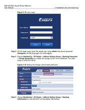
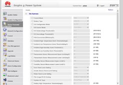
Well, I haven't had success accessing the parameters of the batteries in order to change/increase the charge current limits. Below I show the instructions from the battery manual on how to access the settings by connecting to the Enspire software when connecting my computer to the BMS. However, I show what the Enspire software looks like when I access it, and it doesn't look the same, but more importantly, there is no option to view/change the charge current, or any parameter, of the batteries. The installer is not familiar, so we are still trying to get the supplier to help. I tried to get help directly from Hauwei, that has been a dead end so far. If anyone on this forum is smart on Hauwei batteries, please help! I'll pay :) Thank you

instructions for updating charge current limit.jpg
enspire devices screenshot.jpg
 
Last edited:

diy solar

diy solar
Back
Top