if the battery terminals are reading 56v while charging (which is the set maximum charge voltage), and the battery cells are at 50v (as reported by the BMS device)
One of the two is wrong.
if the battery terminals are reading 56v while charging (which is the set maximum charge voltage), and the battery cells are at 50v (as reported by the BMS device)
Okay, I just did a check with a good amount of sun. Dashboard reporting 56v, charge controller 1 read 56.3v, battery terminals read 55.7v, and BMS reporting 50.0vIf the voltage at the charge controller is significantly higher than the voltage on the battery terminals, you have a high resistance connection - in other words, your cables would be undersized.
No, it is only about 55% during the measurements I'm taking right now.Is your battery just full?
Dashboard reporting 56v, charge controller 1 read 56.3v, battery terminals read 55.7v, and BMS reporting 50.0v
No, it is only about 55% during the measurements I'm taking right now.
I don't think the BMS is the issue because the fact is that the batteries are not full. This delta in voltage is true even when the batteries are fairly low in the morning, call it 30%. Once I get a good amount of sun, this voltages are the norm. For clarification, the battery terminals I'm testing are where the cables are connected to, so if the charge controller is output 56.3v, then wouldn't I expect the battery terminal to read close to that and not the 50.0v reported by the BMS?I would think something is wrong with the BMS. Which one is it?
I will check this when we have full sun for at least 30 minutes, but I don't think the cables have been getting excessively hot.Undersized cabling could limit your charge rate. If that was the case, you would likely be able to feel the cables and they would be hot.
For clarification, the battery terminals I'm testing are where the cables are connected to, so if the charge controller is output 56.3v, then wouldn't I expect the battery terminal to read close to that and not the 50.0v reported by the BMS?
Like @sunshine_eggo said, if you have DVCC enabled, check what the maximum charge current is set to. That will limit the charging power used regardless of what the individual components are technically capable of.
Second, I am pretty confident that the cables going from the charge controllers to the batteries cannot handle 60A.
A screenshot of your VRM dashboard during a sunny period would help a lot (with "show details" enabled).
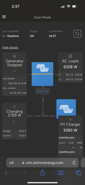
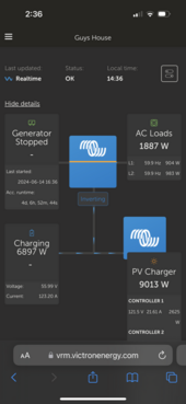
I hear you and I'm not knowledgeable enough to say differently, but if you look at the charge curve, the voltages reported by the BMS seem to be about right for the SOC.Yes, but if you have a meter and it says it's 56V, and your BMS reports 50V, they can't be both true. If your meter is properly calibrated (new batteries as well?), the BMS has to be wrong. With a JK and the like, you can calibrate that - so that's why I asked what the BMS was.
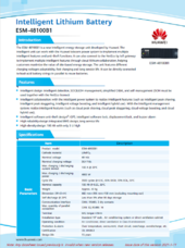
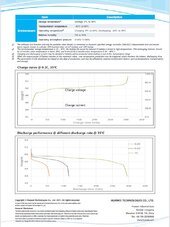
ESM-48100B1
View attachment 222288View attachment 222289
I just got 10 minutes of good sun, but not long enough for me to capitalize on it. I got two screen shots, one at the maximum charge rate I get with 56v set, and two with the AC load increased and showing the charge rate slowing along with the reported voltage dropping. I wasn't able to get a screen shot showing the PV charger higher than 9k with higher AC loads. I will get that screen shot tomorrow hopefully if we have some sun. I know already what it will show, and that is I can have plenty of PV charger watts available, say 12k, but when I lower the AC loads, the charge rate of the batteries doesn't increase, just the PV Charger rate reduces, so the battery charge rate limit is 56v (or 58v when I increase max charge voltage) times 124amps.
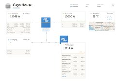
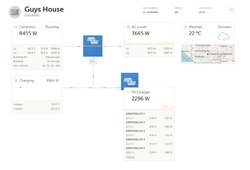
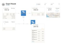
Hello, I think the 56v is just coincidental, but I will confirm on another day when the installer can remind me how I adjust the maximum charge voltage of the battery. We currently have it set at 56v, but we have had it set at 54v and 58v before as well, and I'm pretty sure the voltage at the battery terminals read 54v and 58v when we we charging at the maximum charge rate. Thank you for all of the help!I would still assume that you have the version with a boost converter. It explains the 56V you see, etc. Sorry, I don't have the time right now to dig deeper (it's also 1 AM here), but if it were me, this is where I would start my research. I skimmed the video, and apparently that 56V converter kicks in when there is specific communication missing.
We currently have it set at 56v, but we have had it set at 54v and 58v before as well, and I'm pretty sure the voltage at the battery terminals read 54v and 58v when we we charging at the maximum charge rate.
I don't think the wire sizing/type is the primary culprit of my limited battery charge rate. I have been charging the batteries (generator is running) at their 56v and 124 amps for at least 20 minutes, and none of the wires from the batteries, shunt, or charge controllers are hot. The system has been running for more than a year without issues. I understand that my wires might be undersized, but I don't think that is what is causing the charge rate limit of 58v and 124 amps.Here’s something else to know about Victron.
The MPPTs require pretty specialized wiring. It would be a good idea to check if you installer followed these recommendations.
View attachment 222304
I will ask the installer, but I don't think he will know the answer, and also I think based on the charge curve shown on the data sheet, it makes sense that the BMS reports 50.0v at the SOC when I read the voltage. FYI, I read this from the BMS device from the ESS page of the menu, not from the battery terminals. The battery terminals, when I'm charging the batteries, read pretty close to what the charge controllers are putting out, which is about 56v (what I currently have set to as the charge limit). I will ask him either way, and also about the boost converter.Ask them why the BMS would report 50V, and if there is a boost converter present. It might very well be that this setting also affects the boost converter output.
The max current in the DVCC is set to 160amp. I don't think it is enabled, but I'm not sure.
I agree that the cables may be undersized, but do you think that is what is causing the charge voltage to reach the set limit (56v right now) and also keep the current at 124amps in total?
Turn off DVCC or change the max amps allowed by DVCC and see what happens. To be on the safe side, you could change the max charge amps to a lower value to see what happens.


