diy solar

diy solar

Battery Equalizer PLC-10 with display from Mazava (Unboxing)

coalfield

New Member
Joined
Sep 12, 2021
Messages
72
Arrived today so wanted to share with you initial unboxing on this Battery Equalizer PLC-10 from Mazava
Purchased from AliExpress for around $35, it looked to be exactly what I was looking for.

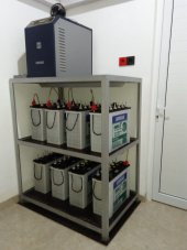
I have 4x12V in a 2P 2S setup for 24v. I have matched batteries but purchased at a different time (within a couple of months) and noticed a few anomalies with voltages so purchased this. I have however been running the Victron Balancer in the last couple of weeks as this was taking a while to arrive.

No issues with the Victron, but this is half the price and having the visible display means I need to pull out the multimeter less and can see where things are at at a glance. Also the Victron seems to only balance when there is around 150-200mV difference. The Victron also required the mid-points to be connected, something I still don't really understand but it did work!

Packaging is minimal to say the least, manual and unit, nothing else. Although not shown in the manual, this is designed to me mounted directly to a rail, it simply clips in. Wish they showed this in the manual, I need to buy a rail for this, but tested on one I have for my battery breaker and it works perfectly, just clips on.

Build quality does not seem amazing, but for the price I think that's to be expected and what counts is if it works.


IMG_2710.JPEGIMG_2712.JPEGIMG_2714.JPEG

IMG_2716.JPEG
IMG_2717.JPEG

For my setup, I figured I needed 2 of these, one for each pair of batteries. "The manual does state 'It can be connected to the battery connected in series for a long time to automatically maintain battery balance without maintenance." I have to say I am not sure what that means with regard to parallel batteries and if long term connection would cause issue? For not I have these connected full time.

Battery setup for Sealed is B03 (default), but can be changed easily to suit a wide range of batteries including lithium. However these are designed for 7-18Vdc.

The balancing current is up to 10A, compared to the Victron which was 0.7A.
The standby current is 7mA compared with the Victron 0.7mA (presumably due to the screen)

The way i connected is like this as per the manual:
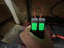


Hbf0e3349d83a402e9c9daa03ff56e8633.jpg

End result is:

IMG_2749.jpeg IMG_2747.jpeg

So far balancing is already good on my batteries, so this has come on for a short period only, however time will really tell how well this works. When balancing turns on an arrow comes on to show which way the balancer is moving current. I have no power meter yet but will give this a test after I have purchased one. One thing i have noticed is the Voltage reads a little higher than my multimeter. It basically seems to round it up as only goes to 1dp, or my multimeter may be off.

Cost is not actually much cheaper than the Victron after buying 2 at least for my setup, however love the fact I have a constant visualisation of battery voltages, and can see when its balancing. Also the balancing current of 10A is a major plus in terms of speed over the Victron.

Will feedback more as time goes on!
 

Attachments

  • IMG_2747.jpeg
    IMG_2747.jpeg
    316.1 KB · Views: 46
Last edited:
So after a month or so of use, I am pretty impressed with the results. I have left these on 24/7 and the batteries are in balance between 0.01V of each other everytime I have tested. I cant really tell how often the balancer is switching on now, since I am usually not there when it happened, but this has been doing a better job than the Victron unit since the deviation is much lower, Victron was more like 0.1V difference.

From a cost perspective it worked out to be about the same price for a pair of these versus the Victron balancer, and I needed 2 but with the more accurate balancing and the screens to show what's going on I would recommend this hands down for AGM.
 
I have left these on 24/7 and the batteries are in balance between 0.01V of each other everytime I have tested.
when you mean you leave these on 24/7, does that mean the balancers remain connected to the battery bank while the battery bank is being charged/discharging?
I have 8 x 12V200Ah FLA tubular battery bank FLA in series (as recommended by the vendor), the max charging current is 50A. Can I leave the balancers connected to the battery bank 24/7 since I read the balancing current is 10A.
I am a newbie at the solar power stuff. Attached is the setup by the vendor. No battery voltage monitor for individual batteries. No equaliser. I am trying to improve the setup.
 

Attachments

  • solar setup.jpeg
    solar setup.jpeg
    41.8 KB · Views: 19
Can I leave the balancers connected to the battery bank 24/7 since I read the balancing current is 10A.
Yes they are connected 24/7, but note they only balance when there is a voltage differential between the batteries, otherwise they are essentially in standby. I am no expert either, but there will be other criteria the balancing would usually happen between a specific voltage range, but are designed to be on all the time so to speak.

The best way to see if you would benefit from them is to check the voltages when they are fully charged and on float. Your hardware may have a balancer built in its hard to see from the wiring.
How about an update on your balancing act. I'm about to put 2 Mazava PLC-10 balancers in service on a 2S2P 24V system.
I have 4 new 12V, 200Ah LiFePO4 batteries to top off and connect. My balancing act seems simple and effective, see photo below.
My Balancing act.PNG
 
Last edited:
I've had a really bad experience with the PLC-10s.
I have 12 300AH 4S3P LiFePO4 batteries. The PLC-10s were installed per the directions. Each 48v bank had 2 for a total of 6.
The first one to go bad was in service working fine for about 6 months. It melted the case and nearly caught fire.
I bought 2 from iSunergy to replace the pair. Things went well for a while.

I started having issues with the batteries cutting out well before they should.
The other day they were down to around 40 percent as measured by a shunt. When the solar started charging them another of the old ones got hot, but seemed to be OK once things settled down. Later I checked that particular bank manually and the batteries were way out. I pulled them and started to top balance. Two batteries took about 250AH and the other two took 50. If I'm doing the math right, that amounts to about 200AH missing capacity.

I did some other things that involved disconnecting a balancer from another bank. When I reconnected it the voltage across the battery read via multi-meter around -8 instead of 13.5ish. I pulled that balancer and noticed that the one beside it had a slightly melted case. I took that one apart and the insides were toast. I took the -8 one apart and it too was toast. I ended up taking them all apart.
I found out that I had two versions of these. The newer version has bigger film capacitors. The ones from iSunergy were different and apparently an updated design. I had no idea till I pulled them all apart today. The only outer difference was the Mazava logo was in color.
Attached are pictures of them. The one with large tan caps are the iSunergy ones. The old one has the x400.

PXL_20230202_031344499.jpgPXL_20230202_030800159.jpgPXL_20230202_030201467.jpg
 
@shiloh.sharps thanks for sharing this, making me want to open mine up to check which version I have. Were they easy to get into?

Mine are the Mazava ones which has me concerned however they have been running over 2 years without any issues I have just left them to get on with it. Not noticed them getting hot, and the power levels across the shunt are hitting 100% daily.

Out of interest what was your wiring setup? Mine are in 24V (2S2P) not 48V so maybe that makes a difference but have to say the instructions to wire these are not that easy to read
 
I've had a really bad experience with the PLC-10s.
I have 12 300AH 4S3P LiFePO4 batteries. The PLC-10s were installed per the directions. Each 48v bank had 2 for a total of 6.

Hi seems a bit odd, can you please post a diagram of your wiring?

Since you’re using 2 units for each bank, you only need to parallel those 2 balancers (parallel wiring on top), and not the whole 6. The 3 parallel battery strings will be balanced automatically.
 
Out of interest what was your wiring setup? Mine are in 24V (2S2P) not 48V so maybe that makes a difference but have to say the instructions to wire these are not that easy to read

Like I mentioned earlier, if you have 2 parallel strings, 24V each, do not connect the parallel wiring on top of the balancers. You only need to have one balancer per each 24V string.
 
I found out that I had two versions of these. The newer version has bigger film capacitors. The ones from iSunergy were different and apparently an updated design. I had no idea till I pulled them all apart today. The only outer difference was the Mazava logo was in color.
Attached are pictures of them. The one with large tan caps are the iSunergy ones. The old one has the x400.

Please is it possible to post pictures again of the 2 PCB versions, front and back, as well as the LCD board, I’m curious about the design. I’m planning to buy a few of those for my 4S2P 48V setup. Thank you!
 
I have been using the HC-01 model from Mazava, seems to work well, and I bought it due to the ability to quickly read the output voltage of each battery at a glance, rather than just an indicator light like the Victron. This model looks even better, but does the background lighting stay on? Or only come on when it is balancing? My eyes are poor and I cannot read most LCD displays unless they are lit.
 
I'll try to answer everyone's questions in one post. Sorry if I miss you. The back lighting does not stay on. The balancers were only connected on the pair servicing the 4 batteries in each bank, no 48v cross connects. They were not easy to get into. The front pops off easily enough. The large toroid transformers and boards are glued in with potting compound. After the first crispy one I really didn't care if I broke them so naturally I got the good ones apart with no problems.
Attached are pictures and diagrams requestedMazava_Diag.pngBattery_Diag.pngPXL_20230202_165314200.jpgPXL_20230202_165249606.jpgPXL_20230202_165212084.jpgPXL_20230202_164940182.jpgPXL_20230202_164845281.jpgPXL_20230202_164813788.jpgPXL_20230202_164658632.jpgPXL_20230202_164618941.jpg
 
I have finished the manual balancing.
The banks serviced by the "old" model PLC-10 were horribly out of balance. Those banks took roughly 300AH each to bring back to full charge @12v.
The bank serviced by the "new" version took 7AH @ 12v. I.E. perfectly balanced.

Now there is a war going on in my head with half of the voices wanting to buy 4 more of the "new" ones.
The other half are shaking their heads and saying "A sucker's born every day.....".
All of them are wondering how to tell the difference without ripping them apart.......
 
this (maybe?) appears to be the newer style "caps"
https://www.aliexpress.us/item/2251832241912909.html?gatewayAdapt=glo2usa4itemAdapt&_randl_shipto=US

RUEF400 PPTC Resettable fuse 30V 4A 4000MA UF400
You are correct.
I did a little research.
From the data sheet of a similar product (couldn't find this exact one):
3. A PPTC device is not a fuse - it is a nonlinear thermistor that limits current. Under a fault condition all PPTC devices go into a high resistance state but do not open circuit, so hazardous voltage may be present at PPTC locations.
4. The devices are intended for protection against occasional overcurrent or overtemperature fault conditions and should not be used when repeated fault conditions or prolonged trip events are anticipated.
Sounds like it's just a matter of time before the updated one catches fire.....
 
So am i understanding correctly that the old design did not have PTCs and the new design does? If that's the case i would consider the old ones 'melting problems' to probably be fixed. It's true that a PTC doesn't do the exact same job as a fuse but they can be perfectly reliable if they aren't constantly cycled across wide temperature ranges. Circuit breakers are likewise extremely reliable unless they're forced to be constantly 'active'. Lots of very expensive cars have rows of PTCs built into their power distribution centers (fuse/relay box) and they never fail as far as i can tell. The failed PTCs i have personally encountered have only been on kids' ride-on electric cars and they seem to fail by erring on the side of caution and limiting current too much or too early. The failed NTCs i have encountered failed open circuit. I am not sure if PTCs tend to fail that way but if they fail 'high resistance' or 'open circuit' that is a pretty 'safe' failure mode.. Lots of transistors fail by shorting and we don't give that a second thought before installing all these devices, so worrying about the reliability of a PTC that exists to protect a transistor if we did not mind the transistor in the first place, is sort of pennywise and pound foolish in my mind. So if the old design did not have PTCs and the new design does, i personally would be happy and relieved to put them right in place of the old ones and carry on. But im making a lot of assumptions about how the PTC is implemented without knowing a darn thing about the circuits. My .02.
 
So am i understanding correctly that the old design did not have PTCs and the new design does? If that's the case i would consider the old ones 'melting problems' to probably be fixed. It's true that a PTC doesn't do the exact same job as a fuse but they can be perfectly reliable if they aren't constantly cycled across wide temperature ranges. Circuit breakers are likewise extremely reliable unless they're forced to be constantly 'active'. Lots of very expensive cars have rows of PTCs built into their power distribution centers (fuse/relay box) and they never fail as far as i can tell. The failed PTCs i have personally encountered have only been on kids' ride-on electric cars and they seem to fail by erring on the side of caution and limiting current too much or too early. The failed NTCs i have encountered failed open circuit. I am not sure if PTCs tend to fail that way but if they fail 'high resistance' or 'open circuit' that is a pretty 'safe' failure mode.. Lots of transistors fail by shorting and we don't give that a second thought before installing all these devices, so worrying about the reliability of a PTC that exists to protect a transistor if we did not mind the transistor in the first place, is sort of pennywise and pound foolish in my mind. So if the old design did not have PTCs and the new design does, i personally would be happy and relieved to put them right in place of the old ones and carry on. But im making a lot of assumptions about how the PTC is implemented without knowing a darn thing about the circuits. My .
Thank you!
I learned a lot from your explanation.
After thinking more about the failures, they likely wouldn't cycle due to over current unless the battery BMS cut out/in.
 
Last edited:
Back
Top