diy solar

diy solar

Battle Born Current Surge Limiter: Anyone using one?

corn18

Village Idiot
Joined
Sep 9, 2021
Messages
680
Saw this on the Battle Born site:

https://battlebornbatteries.com/product/current-surge-limiter/?fbclid=IwAR3xwU7vIIPlJ9iNSFZ8oqJ261fzsiKPksSPkO9iYCXD71C6_MnJl4Usg9M#:~:text=The CSL500 Current Surge Limiter,3.5kW
CSL-PNG-1.png


lightbox-blank.gif
lightbox-blank.gif
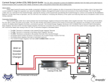
Here's how it's wired:

1660595641206.png

$280 is steep but it would sure help wife proof my RV setup.

Anyone using one? I have one in my cart and ready to hit buy.
 
Last edited:
Its description makes it sound like a glorified pre-charge resistor for $280.

But the giant heat sink and price suggest otherwise.

But the fact that they only show us the EMPTY side of the heat sink makes me suspicious and highly pessimistic that it's worth $280, WHATEVER it is..

I haven't put much thought into this before this exact second but it seems to me like some combination of a zener diode and precharge resistor in series could be paralleled around a battery disconnect such that 'if voltage difference between the two sides of the switch exceeds X threshold, flow current through pre-charge resistor until voltage difference falls below threshold'. When the switch is on it would do nothing. The question then becomes, how big of a heat sink would you need to put on it, because if $270 worth of heat sink is required then yeah, i guess buy this thing. :ROFLMAO:

But im assuming this thing has actual electronics on it and is somehow doing more than being an automated pair of hands placing and removing a 50cent resistor across two terminals. The description just isn't helping me figure out what that is.
This video shows a lot of electronics in between the heat syncs.


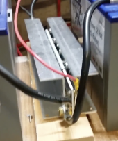
Here's a pic:

Screen Shot 2022-08-17 at 15.22.16.png

This is the meager description from the BB site:

"
The CSL500 Current Surge Limiter is FET-based current limiting device that is to be used with Battle Born
Batteries or Dragonfly Energy LiFePO4 battery packs when they are used in conjunction with large
(greater than 4kW) inverter/chargers. The device is mounted permanently in series between the
negative pole of the battery bank and the negative DC input terminal of the inverter/charger. The device
protects the battery management system (BMS) from damage caused by the initial current spike that is
created when connecting directly to the large capacitors (> 5 milliFarads) that are typically on the DC
input side of the inverter/chargers. The device allows the batteries to slowly charge the capacitors
(within 1 ms). This soft start avoids the high-current shutoff inherent to the BMS of the batteries."

So it seems there are a lot of electronics in there. Since it is universal, I have no problem dropping $280 to wife proof my RV. I ordered one and it will be here on Saturday. Will update how it works.
 
Ok, i see it basically looks the same on both sides anyway as the guts are ‘sandwiched’ between two heat sinks.
So i suppose it needs to be fairly large and expensive because it’s putting a paralleled bunch of large transistors permanently in series with the battery circuit. That means you have to keep stacking transistors in parallel until their combined parallel resistance is low enough to not present an objectionable efficiency loss in a very high current circuit, otherwise they’d be ‘costing’ you something all the time AND generating a ton of heat.

I guess the plus side of it is compared to an actual contactor that would switch a resistance in and out of the circuit, this has no moving parts. Either approach could be automated but this ‘should’ be more reliable long term to go along with the higher cost.

I didnt know it existed before your post, so glad you asked even if neither i or anyone else offerend anything useful in response.. ? I’m going to look into ‘pre-charge’ options further now so i can figure out what complicates things so much to justify devices like this.. in theory the only time your caps would be discharged after initial hookup is if the battery is disconnected from the inverter. I guess lithium BMS’s, especially oversensitive ones from sellers with an actual real warranty, might make that a common enough occurrence to want to create a permanent device in the circuit to prevent damage from a situation which would otherwise almost never happen.

Probably my general newness to the topic is quite obvious by now.. lol
 
Last edited:
You only need to pre-charge the capacitor bank when you hook up the inverter to the battery the first time or if you disconnect/reconnect the inverter from battery all the time. Once you preharge the capacitors, they will stay charge as long as the inverter is still connected to the battery.
So I do not really see any need to spend this much money unless you disconnect/reconnect the inverter all the time.
 
You only need to pre-charge the capacitor bank when you hook up the inverter to the battery the first time or if you disconnect/reconnect the inverter from battery all the time. Once you preharge the capacitors, they will stay charge as long as the inverter is still connected to the battery.
So I really see any need to spend this much money unless you disconnect/reconnect the inverter all the time.

Agree. This is for my RV, so I need something built in. I have a precharge circuit now with a simple resistor, but this should replace that and make it automatic.
 
I am pleased to report that the Battle Born current limiter works like a champ. No more pre charge circuit required. Yeah!!!
 
Battleborn has a great Marketing Team over there.
Wish I had known about their current limiter device earlier. Would have saved me a lot of headaches with BMSs going into protect mode on my RV.
 
Well, I did another experiment with good results. I had a single A/C running on the inverter and all was good. I decided to overload the inverter by turning on the second A/C. When the inverter reset (I turned off one A/C while it was resetting), everything came back on and the batteries were fine. Without the current limiter, when the inverter came out of reset, it would trip the BMS protection on both batteries. Then I would have to reset the BMSs which is fine, but my wife could not do this. Now everything just works.

My next experiment is what happens when I disconnect from shore power. Without the current limiter, the inverter would reset and when it came on, the BMSs would be in protect mode and I had no power at all until I reset the BMSs. I'm hoping the current limiter will eliminate this failure mode as well.

I'm very happy with how this things performs so far.
 
Just so i understand, you’re saying that in the event that the inverter was overloaded by two ac units, upon starting back up it would trip both battery bms’s BEFORE the inverter went down, because of simultaneously trying to start 2 compressors?

And when you say disconnect from shore power results in inverter reset, i assume that means disconnecting from shore power while carrying a load larger than the inverter is rated for? Because at that point there would be no compressor starts if they were already running..

What size is the shore power connection and what size is the inverter? Just trying to understand.
 
Just so i understand, you’re saying that in the event that the inverter was overloaded by two ac units, upon starting back up it would trip both battery bms’s BEFORE the inverter went down, because of simultaneously trying to start 2 compressors?
1. Running one A/C off of inverter
2. Turn on second A/C
3. Inverter shuts down due to overload
4. Batteries are fine
5. Shut off second A/C
6. Inverter resets and tries to turn back on
7. The inrush current from the now discharged inverter caps trips both BMSs
8. No DC or AC power to RV
And when you say disconnect from shore power results in inverter reset, i assume that means disconnecting from shore power while carrying a load larger than the inverter is rated for? Because at that point there would be no compressor starts if they were already running..
I think so. I don't have as much hard data on this event because I never spent the time to investigate thoroughly. Will do some more experimenting once I get the camper to shore power.
What size is the shore power connection and what size is the inverter? Just trying to understand.
50A power connection. Victron MultiPlus II 12/3000/2x120
 
Ok interesting. I can see where you have a large enough shore connection that many inverters would struggle to cope with the same loads the shore connection could handle. The way circuit breakers tend to work you could go past 50a for a decent little interval and that’s getting into crazy town for an inverter-based 120 circuit. 30a shore power less so..I have a 5kw inverter in my rv that can pick up everything the 30a would normally carry, although i wouldnt leave it like that on batteries for any longer than it took me to stand up and turn things off. ?

So the only question i still have then, is why are the caps discharging when the inverter shuts down? Between #3 and #7 in your list the batteries are still connected to those caps, so it seems to me they shouldn’t actually be discharged when the inverter operation resumes. Not asking in an accusatory way, i just don’t understand why the problem you were having exists in the first place.

But im happy that device fixed it for you!
That's a good question. Not sure where the Victron MPII switches power when it resets.
 
Back
Top