diy solar

diy solar

BMS current question

IrishG

New Member
Joined
Sep 16, 2023
Messages
31
Location
Ireland
Just a quick questions so I understand better.

If I have 3 growatts in paralell with 100a max charge current each.
4 x 16s 280k 48v batteries with centralised busbar (not daisy chained)
no coms between inverter and batteries.

Example Scenario
Its a sunny day and solar is strong and doing the full 100a from each inverter. if the batteries are slightly out of balance to each other and 3 batteries get full. Would the remaining battery then get the full 300a charge? and trigger protection from BMS? Or can the BMS restrict current that it accepts via the parameters?
 
The possibility theoretically exists, but it's highly improbable.

If one or more batteries are full, you're almost certainly at the bulk/absorption voltage, which means current is already tapered while voltage is holding steady, so it's highly unlikely that the system is putting out 300A.

Employing a more conservative 3.45V/cell bulk/absorption voltage with a 3.375V/cell float will essentially eliminate the possibility of that happening. Charging to a lower peak voltage at a lower current also optimizes cycle life; however, it will extend your full charge time to about 2 hours after hitting bulk/absorption.
Thanks, so it's quite important that each battery pack is quite close to each other in charge level? Because as soon as one battery triggers the 3.375 float it will slow down charging to the other three batteries from the inverter, even though they themselves haven't hit the cell float level?

Am I understanding that correctly?

No.

Since the batteries are in parallel, they will always be at the same voltage even if they are at different states of charge.

When the battery bank as a whole reaches the bulk/absorption voltage, you will not get 300A. You will get less and less as one or more batteries fill.

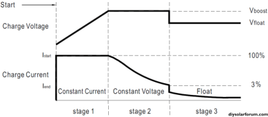
Illustration:

1699206167112.png
Upper line = votlage
Lower line = current.
Vboost = bulk/absorption.

As you can see when bulk/absorption/boost voltage is attained, the current immediately starts tapering and gets progressively lower over time as the batteries fill.

Once the current has fallen off to a very low level, 3% in the example above or 9A in your case, the charger concludes the battery is full and drops to float. The % numbers are intended for lead-acid, but they are close enough for LFP, and your Growatt chargers may behave differently, but not in any major way. The main difference between lead-acid and LFP is that "stage 2" tends to be very short when charging to 3.5-3.65V/cell and about 2 hours when charging to 3.45V/cell. With lead-acid, it's typically 2-4 hours.
 
No.

Since the batteries are in parallel, they will always be at the same voltage even if they are at different states of charge.

When the battery bank as a whole reaches the bulk/absorption voltage, you will not get 300A. You will get less and less as one or more batteries fill.

Illustration:

View attachment 176255
Upper line = votlage
Lower line = current.
Vboost = bulk/absorption.

As you can see when bulk/absorption/boost voltage is attained, the current immediately starts tapering and gets progressively lower over time as the batteries fill.

Once the current has fallen off to a very low level, 3% in the example above or 9A in your case, the charger concludes the battery is full and drops to float. The % numbers are intended for lead-acid, but they are close enough for LFP, and your Growatt chargers may behave differently, but not in any major way. The main difference between lead-acid and LFP is that "stage 2" tends to be very short when charging to 3.5-3.65V/cell and about 2 hours when charging to 3.45V/cell. With lead-acid, it's typically 2-4 hours.
Very helpful and informative as to what happens when they are in parallel, thanks
 
The BMS can’t restrict current. It can only shut inbound, outbound or both currents off.

Thank you for this. I missed that in the original post.

Worth mentioning that without communication from BMS to equipment, a BMS is always an on/off switch. Voltage/charge current goes over? Charge switched off. Voltage/discharge current goes under, discharge switched off.

Only when a BMS can communicate with the equipment to tell the equipment what the limits are can a BMS "regulate" or "control" things.
 
The BMS can’t restrict current. It can only shut inbound, outbound or both currents off.
Some of the new, more expensive, BMS's have a buck switcher they can back down charging current. To use the feature you usually need BMS to inverter communications, so the inverter does not interpret the back off in charge current as a battery absorb charge completion and cause inverter to drop to float voltage.

The main advantage of this is to avoid early charge shutdown by BMS by allowing BMS to back off charging current allowing more balancing time on cells to correct cell imbalance.

A normal BMS has some issues with shutting down charging while still allowing discharge. It must continually reenable charge blocking MOSFET when discharge current gets more than a few amps to avoid overheating body diode in charge blocking MOSFET. The turn off - turn on time for the series pass MOSFET's in BMS is not real fast due to large total gate capacitance so if inverter discharge current drops off and BMS must re-enable charge blocking the time delay may allow a short burst of charging current into battery. If inverter discharge current happens to hover around this charge blocking trigger current the short charge current bursts can add up to overcharging batteries.
 
Without coms is absorption possible with a growatt SPF 6000? I don't see any options for absorption in the settings. Just float parameters. If coms are used is abortion possible via BMS(seplos)?
 
Without coms is absorption possible with a growatt SPF 6000? I don't see any options for absorption in the settings. Just float parameters. If coms are used is abortion possible via BMS(seplos)?
I believe your bulk/absorption voltage is in program 19 “CV” if you are in “US2” program 5 (User defined, lithium). Program 20 is float voltage . You could probably select the correct bms protocol (LI) if you know which code if compatible, but the protocol takes bulk/absorption & float out of your hands and based on what the bms tell the inverter. The problem might be if you select US2 the inverter may not allow enough time above balance voltage to balance your cells. It’s part of knowing your system and making adjustments or adaptations.
 
Back
Top