diy solar

diy solar

BMS not working? Or...? Woke up to sad batteries...

Pincones

New Member
Joined
Oct 31, 2020
Messages
53
So it's 3am here, hopefully I make sense when I type this out. We just switched to lifop4 a few days ago, and we've been thrilled so far. But around 2:30 this morning I woke up to the inverter screaming (we're off-grid, the cabin is powered by batteries). The battery is at 10.0!

Hopefully I have the BMS wired correctly. It came with no diagram and the seller wouldn't give me specs on it. The listing was titled "Daly LiFePo4 4S BMS 12 V 200 400 A" though the unit doesn't say Daly on it. It looks impressive and well built. Anyway, I have the B- cable to the main battery negative, and the P- cable my main system ground. I have the black cable on the BMS clip to cell1-. It's the same terminal that B- is on. Okay. Then red1 to cell1+. red2 to cell2+, etc for the 4 cells. I attempted to follow a chart like this:
and as far as I can tell it's wired properly. I have nothing else connected to my negative terminal.

We had a grey snowy day and the battery was at a not-so-happy 12.1 when we shut down for the night. Figured we'd charge it back up in the morning.

So I have 2 problems I suppose. 1 being that we seem to have had a parasitic draw. I actually turned off the inverter when I woke up to this, and in the 5 minutes it took me to get the multimeter out the battery was back up to 10.26. After about 45-60 minutes it was up to 10.8. So I need to figure out why the inverter was drawing power with nothing plugged into it. I've been using this inverter for 5+ years and have never had a problem. And it hasn't had a problem the last few nights of the new lithium system. The battery has held voltage perfectly overnight so far. I normally just unplug the house from the inverter so nothing is drawing AC power (versus turning the inverter off). ANYWAY. Problem 2 being that the BMS didn't stop that parasitic draw from draining the batteries.

But why didn't the BMS shut the power off to the system? Am I mistaken in how they're supposed to work? If I haven't mussed up my wiring, is there a way I can test the BMS before contacting the seller? I'd really rather hope that I wired it wrong, I'd rather this be my fault.

Hope this makes sense. I'm not human at 3am.

I've got my battery charging now while I do some research, which is probably futile when I'm this tired.
 
Inverters have a small amp draw when on standby. If the inverter had an actual AC load then it wasn't on standy and the draw would be higher.

Have you don't through the settings of the BMS to ensure that the Low Voltage Disconnect is enabled or set right?
 
We had a grey snowy day and the battery was at a not-so-happy 12.1 when we shut down for the night. Figured we'd charge it back up in the morning.

So I have 2 problems I suppose. 1 being that we seem to have had a parasitic draw. I actually turned off the inverter when I woke up to this, and in the 5 minutes it took me to get the multimeter out the battery was back up to 10.26. After about 45-60 minutes it was up to 10.8. So I need to figure out why the inverter was drawing power with nothing plugged into it. I've been using this inverter for 5+ years and have never had a problem. And it hasn't had a problem the last few nights of the new lithium system. The battery has held voltage perfectly overnight so far. I normally just unplug the house from the inverter so nothing is drawing AC power (versus turning the inverter off).
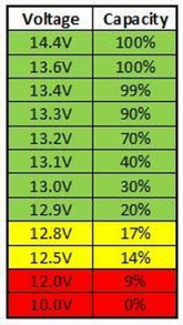
12.1V for LiFePO4 is practically empty, and 10V is dead empty (see chart below). Depending on the size of your battery bank, from a starting point of around 10% capacity, it's not unreasonable that your inverter's idle power consumption could deplete it overnight.

1606405421099.png
 
Problem 2 being that the BMS didn't stop that parasitic draw from draining the batteries.

But why didn't the BMS shut the power off to the system? Am I mistaken in how they're supposed to work? If I haven't mussed up my wiring, is there a way I can test the BMS before contacting the seller? I'd really rather hope that I wired it wrong, I'd rather this be my fault.
A BMS should shut down discharge once an individual cell reaches the low voltage setting. Some/most BMSes (@Dzl, what did we decide the plural was?) have a pack level low voltage setting as well. I'm not familiar with your BMS. Did it come with a manual so you can check the settings as suggested by @HRTKD?

I recommend you also look into installing a shunt-based battery capacity monitor so you can have your state of charge available at a glance. You can go budget with something like the AiLi battery monitor or go up market with a Victron. Shop around for what fits your budget and needs.
 
  • Like
Reactions: Dzl
Yes I realize 12.1 was super low. Rather than run the generator while I'm trying to sleep I was going to charge it in the morning. But instead that happened at 3am :p I got them back up around 13v before turning the generator off and going back to bed. With the inverter off, it held its voltage til morning. I'm continuing its charge now and not using any power from it.

Good to know that the inverter might just have a passive trickle draw, though it's not something I've ever noticed before on the lead acids. Maybe it was combo of low voltage + the trickle draw that depleted them? Because the last few nights they haven't dropped a single point of voltage overnight, and it's typical for me to just unplug instead of hitting the off button (force of habit, the inverter used to be upstairs but unplugging the house was easy from the main room, laziness). Normally they're above 13v going to bed.

The BMS did not come with any paperwork, and I asked the seller for specs and info on it and was ignored (edit; I've asked the seller again for the 3rd time what the specs are. They replied "There is no temperature regulator in the BMS. What specs are you talking about?" e_e So I gave them specifics and they said they'd get back to me later today...). I purchased it anyway because we needed to get the old bank retired and the new battery functional, and this was the only BMS rated for my inverter's draw capacity I could find shipping from the USA (which meant not waiting a month or three for it to arrive). I got it on ebay.

How can I test it to see if it's working? Intentionally deplete the bank while I'm monitoring it and see if it shuts off?

I do have a shunt in my system, but I can't keep an eye on it when my eyes are closed ;)
 
Last edited:
What would the damage to the cells look like with over discharging? I'm still nervous about what the implication of last night is...
 
What would the damage to the cells look like with over discharging? I'm still nervous about what the implication of last night is...
Hard to say because we don't know how low any individual cell got when the pack was at 10V. The prevailing guidance I've read is that a BMS should be set to not allow individual cells to go below 2.5V. I've read various articles and papers that indicate that as long as a cell doesn't get below 2.4V - 2.2V it's not likely damaged. I don't plan on letting mine get that low to test it.

Anyway, I'm definitely not an expert and all of my BMSes are programmed to cut off when any cell hits 2.5V so I've not encountered an issue like yours. Let's see what some others with more battery smarts have to say: @electric, @snoobler
 
You said inverter was "screaming" and also that you shut it off before going to bed, which is it?
Inverter LVC at 10V is perfectly normal and battery at 10V is perfectly OK, but fully discharged.
Assuming your BMS is working and wired correctly I think it simply did not have a chance to kick in just yet.
It probably would have pretty soon, but you beat it to it by your fast reaction.
Nothing bad happened here, everything probably worked as designed.
You can allow BMS to go below 10V and see when it kicks on, but don't go below 8V for too long.
Short period below 10V is fine, just not for days at a time.
Even small inverter idle draw will drain the battery from 12V ( almost empty ) to 10V ( empty ) within a few hours.
I unplugged the AC cord from it before bed- so it was powering nothing. It was still "on" and it has a low voltage warning if its DC power source hits 10.0. So the inverter REALLY saved our butts on that one.

That's relieving to here that it's likely we didn't cause too much damage. I tested each cell last night after we shut down power for the day. I took the whole system apart, disconnected the BMS, and isolated the cells for testing. Before bed every cell was 3.30v, and the next morning they were the same. Phew. We were worried we'd see one or more cells deviating badly. It's hard to read about this stuff; like I can read plenty of articles that say "10v is 0%, critically low, never do that, bad for batteries" but never any details on WHY. What is the physical function, what's going on in the batteries and how is the damage being caused. I'm still a little bit stuck in my "lead acid" mode of thinking with these batteries. We're getting used to the voltage curves and norms, and redirecting our maintenance thoughts, like "batteries need a deep power charge of high amperage now and again to stir em up".

So we're in a new place with the 2 problems. The inverter problem is still a problem. This 2000/4000 watt pure sine wave inverter is now SUCKING power from the battery. Yesterday, the day after the 10v night, we had to run the generator every 2 HOURS for a few hours! We'd get the battery up to 13.4+ and shut the gen down and it would just plummet. 12.4, 12.2, 12.1.... okay time to turn the gen on again. We were pumping 30+ amps into the batteries on and off all day. It was distressing because we thought the cells were toast. Which is why I isolated everything last night to test.
This morning we had held perfect 13.2 voltage through the night (still a perfect 3.30 per cell). We had a sunny morning and the charge controller read an incoming 7 amp. I turned on the inverter. The house wasn't plugged in, nothing was running, I just hit the power button. With 7 steady amps coming in, the battery's voltage starts ticksing down. That idle inverter just slowly sucked the power down. I'm no electrical engineer, but I assume that 7 incoming amps and a dropping voltage meant the inverter was pulling more than 7 amps idling. We've never had an issue with the inverter before, even in the first few days of the new battery. I never thought to check if a lithium battery had to be compatible with a special inverter. I hope not!

So we switched to an old puny 250watt inverter and have been running that all day. Sunny, beautiful day, happy battery, no power woes. We're going to keep trying to diagnose the inverter, play with the wiring, troubleshoot, etc.

But that brings us to the other BMS problem, or potential problem. We had over 30 amps coming into the battery today for several hours. It refused to budge above 13.9v with precious little power usage. We don't seem to be able to bring it above 14v. On a sunny day combined with generator power we can pump close to 100 amps into a system if need be. We didn't do that. But we can if we need to. Anyway.
So I didn't top or bottom balance the cells because my BMS supposedly has an active cell balancer. The cells stayed wired to the BMS for a few days before we put the battery into action. So from what I understand, that active cell balancer should hopefully take care of that. If what I understand is correct, then either the BMS hasn't actually balanced the cells, so the battery can't get above 14v, or the BMS is shutting off current at 14v. Oooooor maybe we need way more than 30 amps to push this battery that high? The "C rate" charging figures are still new to me, so if someone can explain charge amperage needs for this battery size I'd greatly appreciate it.

If what I understand isn't correct, then maybe I just need to manually balance them.

Thoughts?
 
Last edited:
What size batteries are you using?

Are you using a monitor with shunt to see ah in/ ah out? See actual SOC %?

If I hookup my generator and use it with my inverter/ charger I'll set it to charge at 100a (My absorb voltage is 14.1 or 14.2 depending on season). For my 500ah bank charging at 100a if at 50% SOC it would take 2.5 hours roughly.

Depending on what your size your batteries are and what SOC a steady 30a should charge in x amount of hours.

Something to remember is if you properly top balanced your batteries they should stay in close proximity of voltage between cells. As your cells charge and get near full you could have a runner cell that shoots up faster than the rest. Maybe your bms is shutting down charging because of one cell?

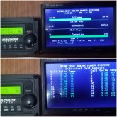
Can you see individual cell voltages on a display while being charged? Something like this as an example, cell voltages are in a constant flux.
20200310_122237.jpg
 
Did you top balance the cells before you put them in series? and as asked what size cells?
 
OP didn't top balance, so that's one potential issue. They also state that cells are at 3.30V, so that could conceivably be only in the low 40ish% charged. So they could just keep charging with the genny to get them as full as the BMS will allow and recalibrate the shunt based monitor to 100% so they can better monitor the situation. Their BMS reportedly has active balancing so it might even things out over time with enough cycling.

The biggest issue to me appears to be that the inverter is sucking down the bank while just idle. That doesn't make sense, so that sounds like it's broken and it's making it more difficult for the OP to understand what's going on with the low state of charge battery bank.

I'm still a little bit stuck in my "lead acid" mode of thinking with these batteries. We're getting used to the voltage curves and norms
Being stuck in lead acid mode of thinking is clouding things. The charge and discharge voltage curve for LFP is very flat. So having your bank at or a little over 13V likely means it's really low whereas that would be good for lead acid. Check out the chart I posted above, and read this article, paying attention to the charge and discharge voltage curves to get a better understanding of how different they are than your old lead acids. You've gotta get a lot more juice into your bank to get it full or you're just going to be playing in the bottom 1/3 of the bank's capacity.

As others have indicated, it would be helpful if you supplied some additional details about your system, particularly the size of the battery bank in Ah. Then it's a straightforward calculation to determine the expected charge time given your 30A genny-based charging.
 
My shunt is just a voltage monitor, it's pretty basic, allows me to see where the battery voltage is at a glance. It sufficed for my lead-acid bank. I'm looking into getting a better one. The BMS did not come with any read-out/monitor options. I have to get in there with a volt meter to manually check cells.

I did not top or bottom balance as the BMS is supposed to have an active cell balancer in it. I watched and read about the ACB's and was left with the impression that it would do the balancing for me. How many cycles is "enough cycles" though, is a good question. They've been employed for about a week now, and aside from the 10v night, the battery generally stays between 13.0 and 13.4.

What are the best ways to test the functionality of the BMS? We haven't been able to check it's over-voltage shut off as the cells haven't climbed that high yet. The bank getting down to 10v makes em nervous that it's low-voltage shut-off isn't working. Everything i've read has left me with the impression that 11.5v is standard on BMS's. I suppose if it doesn't risk damaging the cells we could let it drop below 10.0 and see if/when the BMS kicks in... I'm STILL waiting to hear back from the (terrible) ebay seller on specs.
What about balancing? I suppose I could deplete just 1 cell and then hook it all back up and see if it climbs back up. But then, the cells already hold perfect voltage when isolated, without even a 0.01 variance in voltage. So does that indicate that they are actually balanced?
So, if the BMS 'does' have a balancer in it, and it's keeping every cell at a perfect voltage (even though they arrive at perfectly aligned 3.26v per cell anyway), if I then top or bottom balance it (which from what I understand would put each cell's voltage out of whack in order to ensure they all reach 100% OR 0% simultaneously, despite internal variances?), would the ACB 'unbalance' that in an effort to re-align the cell voltages? Or have I got balancing all wrong? x_x

The cells are 280ah, new.
The battery has seen 30+ amps coming in for over 3-4 hours at a time at peak hours, with 10-20amps coming in when not at peak, making for 8-10 hours days of active charging. It's had many full days now of active charge coming in, but still won't breach 14v.

The cells usually rest at 3.30v over night, after charging by day and usage before bed. During the day with active charging they reach 13.8-13.9v. I was uncertain as to why they won't charge any higher. So if the BMS is *very slowly* balancing the cells, or is simply not balancing the cells, that's probably the problem, as I assumed it would've balanced them by now. But I really don't know I guess. Some of the videos I watched showed ACB's working rather well in real time, where I would assume that a full day of solar charging would allow for most of the balancing work to complete.

The inverter does seem to have a problem. The little one we swapped it out with is doing the job well and the batteries are not dipping below 13v with active use and no active charging. We only run a handful of things most of the time; small monitor, solid state computer, a few lights, a device charger, and maybe a cordless tool battery charger or printer intermittently. The big inverter is there for when we wanna run power tools or the blender or something. Anyway. The big inverter is sucking juice from the batteries with just idle process. I hope it's not dead, but it had a good long run, I suppose.

So I'm trying to read more and understand C rates and such for charge times. Don't know how to term that right, sorry. But if what I understand is correct, if my 280h battery is at 50%, it would take roughly 4.5 hours to fully charge it with 30amps coming in? At this moment it's at 30%, so if we have roughly 30 amps coming into it on our nice sunny day today, it would theoretically take 6.5h to reach 100%. I will play with this and monitor it's rate of charge compared to what's coming in today and if it behaves predictably.
 
Last edited:
My shunt is just a voltage monitor, it's pretty basic, allows me to see where the battery voltage is at a glance.
Yeah, you're gonna need a Coulomb counting battery monitor for these. I gave you some options in post #4.

I did not top or bottom balance as the BMS is supposed to have an active cell balancer in it
Let's set this aside and come back to it later after we tackle some other aspects.

What are the best ways to test the functionality of the BMS? We haven't been able to check it's over-voltage shut off as the cells haven't climbed that high yet. The bank getting down to 10v makes em nervous that it's low-voltage shut-off isn't working. Everything i've read has left me with the impression that 11.5v is standard on BMS's. I suppose if it doesn't risk damaging the cells we could let it drop below 10.0 and see if/when the BMS kicks in... I'm STILL waiting to hear back from the (terrible) ebay seller on specs.
I've recently come across some Daly BMS specs that seem to default to 2.2V as a cell low voltage cutoff (I'm trying to help locate a manual/instructions for your model). So if yours is in that camp, it would explain why it didn't cut off discharge before your inverter. But let's set this aside for a bit as well.

The cells are 280ah, new.
OK good. Now we know how big the bank is. So we can start doing some math.

The battery has seen 30+ amps coming in for over 3-4 hours at a time at peak hours, with 10-20amps coming in when not at peak, making for 8-10 hours days of active charging. It's had many full days now of active charge coming in, but still won't breach 14v.
Let's start looking into this. If your inverter was malfunctioning as you described, it was stealing a good portion of the charge current so you weren't really getting as much charging of your battery bank as you thought.

Now that you've removed the inverter draw from the picture, you are going to have to charge for about 10 hours from when your bank was dead empty to get it full again if you are charging at 30A.


Let's talk about your charging sources.
1) What are the specs on the battery charger/converter you are using when charging from the generator? Does it have a multi-stage charge profile or is it just a power supply with a preset max voltage etc? We need to know what you're using to determine if you'll ever get the bank above 14V with that charging source.

2) What are the specs and charge profile settings for your solar charge controller (SCC)? We need to make sure those are set appropriately for your LFP bank as well.


Once we know more information the picture will get clearer as to what is really happening. Right now I don't suspect your BMS or lack of balancing as primary drivers of the behavior you have experienced. I suspect that you have been severely undercharging the battery bank due to the overly large inverter draw, and possibly also due to inappropriate charger profiles (TBD when you supply the info).
 
I did not top or bottom balance as the BMS is supposed to have an active cell balancer in it. I watched and read about the ACB's and was left with the impression that it would do the balancing for me. How many cycles is "enough cycles" though, is a good question. They've been employed for about a week now, and aside from the 10v night, the battery generally stays between 13.0 and 13.4.
BMS balance in the milliamp range so if the cells are out of balance it could take years to balance

are you using a lead acid charge profile, if so they are designed to lower the charge once the get closer to full charger and since your batteries have a flat voltage they would appear to absortion phase way too early.
 
1) What are the specs on the battery charger/converter you are using when charging from the generator? Does it have a multi-stage charge profile or is it just a power supply with a preset max voltage etc? We need to know what you're using to determine if you'll ever get the bank above 14V with that charging source.
If I'm charging from the gen, I use a converter power station (like for HAM radios) that peaks at 30 amps and has manual/adjustable variable voltage. I run this through my charge controller. Works awesome. We went this route because, with the lead acids at least, it was hard to find any 'battery charger' that could actually push more than 20amps. Even our regular-old 'car battery' chargers rated for 20 amps would barely push 6 into the batteries on their highest setting. But this little power station does an awesome job of actually converting that AC to DC and pushing high amps through. The charge controller ensures that power is being used appropriately on the batteries. We also only do this when we're home and the process naturally gets monitored. We don't want to use the gen more than we need to, and we only use it when we're home and have little power (night time, before bed, sitting around, etc.) It never runs like this while we're not home.

If I'm charging from the panels, we have a 750~ watt array. This time of year we usually get 300-400 watts during peak hours out of it unless we've really got a gorgeous clear day, then we may hit 500+

I can run the gen in tandem with the panels if I need lots of amps with the array by using 2 programmed charge controllers, one for each power source.

2) What are the specs and charge profile settings for your solar charge controller (SCC)? We need to make sure those are set appropriately for your LFP bank as well.
I programmed the charge controller I'm using based on the specs sheets I found on this site. I'm zipping around in browser tabs trying to find the specs I used but for some reason can't find them now... It doesn't have the specs spelled out but I did post a question about it here;

I'll keep looking for either the specs sheets I used, or my actual controller's manual, wherein I wrote the specs down for reference.
 
The cells are 280ah, new. The battery has seen 30+ amps coming in for over 3-4 hours at a time at peak hours, with 10-20amps coming in when not at peak, making for 8-10 hours days of active charging. It's had many full days now of active charge coming in, but still won't breach 14v.
This is really simple math, you are not charging long enough to get a full charge. Your batt was empty, so it would take 9.3 hours at 30A to fully charge. You state periods of 30A, but not for full 9 hours, so your average maybe 15A, which means over 18 hours to a full charge. You got as high as 13.9V ? You should keep charging for as long as it takes to eventually see voltage climb up.
One thing to bang into your mind is how non-linear voltage curve is. It just stays stupidly flat while sucking up amps, it seems unreal, it makes you scared, you think something ain't right. It's all in your head. Forget about voltage between 13V and 14V, it means almost nothing. Watch the amps and the time, i.e. count your Coulombs. That's all that matters.
Also, get yourself a DC clamp meter and measure idle into inverter on DC input. If you see more than 2A then something is fishy with your inverter. Idle power doesn't go into 4th dimension, it goes into heat. Something must be getting warm in the inverter if no useful work is being done, but amps are being sucked.
Again, it's all about amps and hours, voltage is not as important, unless it's below 10V or above 14.6V.
 
What about balancing? I suppose I could deplete just 1 cell and then hook it all back up and see if it climbs back up. But then, the cells already hold perfect voltage when isolated, without even a 0.01 variance in voltage. So does that indicate that they are actually balanced?


that's probably the problem
Don't think in terms of problems where there are probably none. So many newbies ruin their cells or make problems when there weren't any, just because of mindset that something is wrong. Don't deplete 1 cell, there is no point in doing it until you know for sure.
Here is a simple path:
1. Charge until over 14V ( 14.2V - 14.4V ) or until BMS kicks in and stops charge.
2. Quickly measure each cell before time passes where voltage drops naturally.
3. See if 1 cell stands out from remaining 3 by much more than remaining 3 from each other. If highest cell is above 3.6V while lowest cell is below 3.4V, then your pack needs some balancing. If lowest cell is above 3.45V then you don't need to balance.

Rule of thumb is to have lowest cell above 3.45V OCV ( open circuit voltage ) right after charge is finished, while highest is below 3.65V at the same time. No need for perfection. Perfect is enemy of good enough.
 
But then, the cells already hold perfect voltage when isolated, without even a 0.01 variance in voltage. So does that indicate that they are actually balanced?
Voltage difference only matters when at fully charged or fully discharged state. In the middle of SOC this difference is meaningless.
No matter how close cells are in the middle, they will spread out at the end, but it doesn't mean a problem. There is no perfection and no need for one. See my post above for good enough balance rule.
 
Awesome replies, thank you so much. I've been gulping down articles on LFP's (much like I did before buying, but reading before putting into practice only teaches you so much). I stuck the LFP voltage chart up by my batteries to help retrain our brains about it.

Tomorrow should see more full sun, we'll track the amps we're getting and see if we can combine the panels with the gen for a true full day of charging and get them to 14.4 and test.

Thanks :D Super happy to be learning more!
 
I stuck the LFP voltage chart up by my batteries to help retrain our brains about it.
Most LFP voltage charts are garbage. Voltage interpretation depends on charging or discharging, at what rate, where exactly it's being measured, etc. Too many variables involved to accurately interpret by voltage. Accuracy comes below 10% and above 90%, anywhere in between is a wild guess. Don't get hung up on voltage too much, get yourself a Coulomb counting SOC gauge.
 
Found my manual and notes, this is what I have programmed on the CC:
Over-voltage disconnect 14.7
Charging limit voltage 14.6
Over voltage reconnect 14.6
Equalize charging voltage 14.4
Boost charging voltage 14.6
Float charging voltage 13.6
Boost reconnect charging voltage 13.3
Low voltage reconnect 12.0
Undervotlage warning reconnect voltage 11.5
Undervoltage warning coltave 11.4
Low voltage disconnect voltage 11.0
Discharging limit voltage 10.5
Equalization Duration 0 min
Boost duration 180 min

Questions; the MT50 monitor and my Epever unit both have a battery current readout. Is this any different than an ammeter/coulomb monitor?
 
Last edited:

diy solar

diy solar
Back
Top