diy solar

diy solar

DIY 280AH battery JK BMS JK-PB2A16S20P Canbus to SMA 5048

@kommando

Do you know if the inverter will communicate via can with the sunny island and at the same time communicated with solar assistant?
That is my next task, this looks to be the closest solution so far. I have all the parts but it looks like ver 1.2 is broken so will start with ver 1.1 .


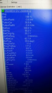
SOC went to 100% before 55.2V met, charging still going as voltage 55.2V is not met but still 55.0V. SI still has Frequency at 50htz so full output from the PV inverters.
 

Attachments

  • SDC 100% SOC but still charging.jpg
    SDC 100% SOC but still charging.jpg
    106.1 KB · Views: 9
SOC went to 100% before 55.2V met, charging still going as voltage 55.2V is not met but still 55.0V. SI still has Frequency at 50htz so full output from the PV inverters.
Thats wild. Where is the 55.2v set? I thought that setting was unavailable if your battery was set to lithium?
 
Set on the Jk BMS +1V as the SI takes 1V off so JK is set to 56.2V and the SI takes that as 55.2V.

See post 40

I only changed Vol Cell RCV to 56.2 / 16 ie 3.513, I kept all the others as was when I wanted 3.45v at my target V.
 
Set on the Jk BMS +1V as the SI takes 1V off so JK is set to 56.2V and the SI takes that as 55.2V.

See post 40
Oh! So jk bms is reporting 100% but still sending a charge command to si
 
Oh! So jk bms is reporting 100% but still sending a charge command to si
Yes the SOC the JK reports is ignored by the JK and the SI, the target voltage is the sole arbiter of the charge rate. You get an over voltage to 55.5v as the SI ramps up the frequency but that is well within the LFP voltage window (remember the JK is looking for 56.2V) but then it drops back as the PV inverters drop their output. It then stabilises at 55.2V as the SI adjusts the frequency to keep to that target. Later once the sun weakens the volts will drop slightly and the SI will drop the frequency and full PV output will be allowed.
 
Today I saw the JK float setting engaged and the JK lower voltage target was sent to the SI which then throttled the inverters until the voltage dropped to the lower target voltage.
 
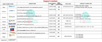
List of Canbus and RS485 protocols with inverters supported, take with a pinch of salt. They list Victron Canbus as 500K but its 250K, they say they tested it but is the 500K a typo or is it actually 500K and will not connect. Need to try that FSS one that is for SMA next time I go off grid for testing and report back.
 

Attachments

  • Canbus RS485 to Inverter protocols.jpg
    Canbus RS485 to Inverter protocols.jpg
    448.4 KB · Views: 10
SI5048 works with JK Canbus FSS-connectingbat-ti-en-20w, which is the SI 6.0H-11 SMA Canbus protocol.


Only difference seems to be the loss of 1% battery SOC at times on the SI5048, when you read the SMA Canbus protocol linked to the FSS you can see the Batt SOC is high resolution and is to 0.1%. So depending on when the JK calc of SOC % rounds to nearest 1% vs SMA you get a mismatch.
 
Back
Top