diy solar

diy solar

Boater, aiming to build safe and stable 12V consumer Powerbank for boat.

thrusters etc.

Any concerns i need to take into considerations regarding this ?
Well some of those are fairly high current. One HP is ~768W, and some of those thrusters are way above 1HP

So I would study up on that. 12V cabling to accomplish that load… fuses to protect from a woopsie etc
 
No thete is no problem with LFp starting engines. The primary issue is most bms are not set up to support high current short time transfers it needs a specialised bms thst can manage the start current. The lithium is a. Ideal starter battery
Ok, so for the BMS issue, is the problem that the BMS is not able to handle rapid high current draw/cutout that will happen when starting or using other high current draw equipment ?, and if so is there any BMS out there that will support this ?
Also have decided to add 12V heat foil with thermostat to the battery enclosure as i live in Norway and is using the boat during the winter.
 
Well some of those are fairly high current. One HP is ~768W, and some of those thrusters are way above 1HP

So I would study up on that. 12V cabling to accomplish that load… fuses to protect from a woopsie etc
The thruster is 12V 4,4Kw, cabling to it is 95 mm2.
When it comes to fuses, i guess it would be a good idea to have a 250A fuse between BMS and LF280K battery cells, this way the cells are protected even if the BMS fails ?
 
But do not solder them especially in a boat! Crimp and seal them properly.
Normally i crimp first, then solder afterwards, thought that might be better with both since the connection then would have better conductivity and no potential for water to come in..?
 
On a banks current draw potential its not only the lug surface area and bolt size but the internal plate buss size and ability to shed heat - yea, lifepo batteries have low internal heating but locked in case/holder/compartment in a marine hull in warm water... every degree rise starts eroding life cycle counts.

anyhow, the popular prismatic cells getting imported now don't have much
metal - small lug contact area, small bolt & threaded lugs plus (perhaps) slightly exaggerated constant/surge current specs - make paralleling 12v strings a safer bet once looking to power thrusters and other high amp draws.

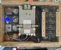
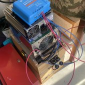
Attached is photo of my 90lb 300Ah 12v bank, 600A discharge 900A peak rated bank - for this application there is a 120BMS and a 2000w LF 120VAC inverter mounted over the Lexan top shield. Oh, and $80 worth of QNBBM dynamic balancers that have been constant duty for two years with zero problems, the BMS balances on charge only and between the two the cells are =/< a thousandth volt difference 99.9% of the time...

(edit) plus a 20A isolated dc-dc charge converter as icing bling as I was finishing building the bank...

((edit: 14mm bolts and 4/0 cell interconnects & 1/4" copper buss bars))
 

Attachments

  • 5680C85C-8FAA-4183-9531-3ADF70569B7C.jpeg
    5680C85C-8FAA-4183-9531-3ADF70569B7C.jpeg
    588.4 KB · Views: 15
  • E74DDB2D-B20B-4DE3-825B-03B9CA6288B2.jpeg
    E74DDB2D-B20B-4DE3-825B-03B9CA6288B2.jpeg
    247.3 KB · Views: 14
Last edited:
So, i have decided to build 2 x 12 V battery`s
Anyone have suggestion for a safe and good 4S 200A BMS with active balancing.

Will also install heat mat/foil in the battery enclosure, but i guess the cheapest and easiest way to do this is just to do this with separate sensor/controller.

Jobba
 
thruster is 12V 4,4Kw
350A+
guess it would be a good idea to have a 250A fuse between BMS and LF280K battery cells, this way the cells are protected even if the BMS fails
The fuse(s) protect the wires not the battery
Either way the BMS’s usually fail open
Normally i crimp first, then solder afterwards, thought that might be better with both since the connection then would have better conductivity and no potential for water to come in
You do a proper crimp and then seal it. That protects against water infusion.

Soldering makes the wire stiff- and vibration, flex, and movement can then break that wire. That’s a fire hazard. ABYC calls for proper sized wiring and cables with crimped connectors/terminals for that reason. Soldering negates the margin of safety- don’t solder. Buy good crimpers and do it correctly and no problems.
 
350A+

The fuse(s) protect the wires not the battery
Either way the BMS’s usually fail open

You do a proper crimp and then seal it. That protects against water infusion.

Soldering makes the wire stiff- and vibration, flex, and movement can then break that wire. That’s a fire hazard. ABYC calls for proper sized wiring and cables with crimped connectors/terminals for that reason. Soldering negates the margin of safety- don’t solder. Buy good crimpers and do it correctly and no problems.
Agree crimp properly don’t solder
 
So, i have decided to build 2 x 12 V battery`s
Anyone have suggestion for a safe and good 4S 200A BMS with active balancing.

Will also install heat mat/foil in the battery enclosure, but i guess the cheapest and easiest way to do this is just to do this with separate sensor/controller.

Jobba
Anyone that can recommend a good BMS ?
 
Back
Top