diy solar

diy solar

Brand new JK BMS won't start

Kokireg

New Member
Joined
Apr 30, 2022
Messages
36
Hi everyone,
I'm building a new battery (I've already built some)

I received my EVE280K cells
I did my top balance.

Then I wanted to connect my JK BMS (brand new) but it does not want to start
for information a small bracket was bent on the BMS (but nothing to do I think with the problem).

with the BMS I have the LCD option (small screen)

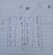
I have 13.31 V of voltage at the battery.

I have of course tested the voltages at the output of the balance wire before the connection.

I tried to launch a charge on p- (bms) and B+ (battery) of 13.4 V but the charger does not deliver any amps.
I pressed the button on the screen but it does not start.

Here is a video:
 
To startup JK, there should be a voltage potential of >2V between B- and P-.
Older JK (8x hardware version?) needs 5V

You achieve this using a power supply, set 2V higher than your battery pack. Connect Supply Positive to B+ of the Pack. Connect Supply Negative to P-. And within 3 seconds it should turn on. This is achieved naturally when pack is connected to an active SCC.

PS. I dont use the pushy button.
 
Last edited:
Looking at the motherboard we see that it is version 9
Moreover I have the small LCD with the power button so I thought that by pressing the button the BMS should turn on

My battery is at 13,31 V so I have to put a load between P- and B+ of more than 15,31 volts
Is it safe for my battery?


thank you
 
I contacted Nami (via whatsapp), very nice.
They told me that the version of my BMS is an old version compatible only 8S, that I need to put a DC booster DC 12V-24V.
The old versions have 5 interfaces (connection) compatible 8S.
The new versions have all 6 interfaces compatible 4S.
 
This is an old cell that I no longer use. It was part of an old battery I made that had problems.
 
I have a similar problem.
I connected +5V to P- and -5V to B- but no success?
Must be cells connected before the BMS can start or +5V to P- and -5V to B- is enough for starting?
 
When I first powered my JK 24S BMS (V10xG), I have:

1658453961701.png

  1. I rigged up a 4 cell LIon battery pack (Ryobi cordless drill) (my LiFePo4 cells hasn't arrived yet)
  2. B0 connected to Battery Negative (as shown above)
  3. B+ connected to Battery Positive (as shown above)
  4. Did not connect B1, B2, B3, B4 as I did not disassemble the battery pack
  5. Using an adjustable power supply, I set it to ~ +2V; connected the positive to B- and negative to P-
I was suppose to slowly adjust this power supply to +5, to witness the power up transition, but my JK simply powered up the moment I connected it.

On my running setup (16S), I dont need an external power supply to power up JK.
Most of the time, my 16S Battery Pack would settle between 54V~54.4V (3.375~3.4V per cell).
And my Deye is configured to send ~56.8V (Float Charge Voltage).
(CAVEAT: Occurs only when PV is harvesting, or when Grid Charging is activated).
Thus when I connect Deye at B+ and P- to Battery as shown above (disconnect switch not shown), JK would see ~2V at B- and P- and immediately powers up.

Thus my current procedure of turning on two JK BMS on my running setup:
1. Both JK OFF, all Battery Breaker/Switches OFF position
2. Deye thinks my battery are full and sends 56.8V (Float charge voltage) between B+ and P-
3. I turn on Battery Switch #1, JK BMS#1 turns on and immediately starts charging after bootup.
4. I turn off that Switch #1 (this will bring Deye back into Float Charge mode), but JK BMS#1 is still ON.
5. I turn on Battery Switch #2, JK BMS#2 turns on and immediately starts charging after bootup.
At this point, both JK BMSes are ON.
6. I then turn on Switch #1; both JK BMS are connected to Deye.
Caveat1: Deye Inverter thinks I have two fully charged battery packs because of #2.
Caveat2: If your SCC does not send Float Charge Voltage (like Deye does) when there is no connected Battery, this procedure will not work for you.

NOTE: My JK BMSes are Hardware Version 10.XG
Maybe this is why I only needed +2V to wake them up.
1658455498921.png
 
Last edited:
connected +5V to P- and -5V to B- but no success?
It should be +5 on B- and -5 on P-

During Charging, SCC Voltage is higher than Battery Pack (B+ to P-).
B- is at higher Potential than P-.
1658481743620.png
You need a higher potential* at B- than P- to wake JK up.
This Voltage Potential is naturally present when you connect it to an SCC**.

*Depends on hardware version; could be +2, could be +5, etc.
**Will not happen to some SCC that requires a battery present to initiate charging voltage.

NOTE: I added B+ and B0 on this diagram to imply these are NECESSARY to power JK.
 
Last edited:
Thanks a lot for your instructions.
  1. I rigged up a 4 cell LIon battery pack (Ryobi cordless drill) (my LiFePo4 cells hasn't arrived yet)
What voltage was that battery pack?

And do you think the JK BMS would start without any batteries connected?
But only by putting +5V to B- and -5V to P- ?

Thank you for your reply
 
What voltage was that battery pack?
1658480840088.png
+14V 4-cell Lithium Ion (not LifePo4) cordless drill battery pack

And do you think the JK BMS would start without any batteries connected?
But only by putting +5V to B- and -5V to P- ?
NO.

I repeat:
  1. I rigged up a 4 cell LIon battery pack (Ryobi cordless drill) (my LiFePo4 cells hasn't arrived yet)
  2. B0 connected to Battery Negative (as shown above)
  3. B+ connected to Battery Positive (as shown above)
  4. Did not connect B1, B2, B3, B4 as I did not disassemble the battery pack
  5. Using an adjustable power supply, I set it to ~ +2V; connected the positive to B- and negative to P-
The terminals involved were B0, B+, B- and P-. The Sense Wires were not connected. THESE are the bare minimum to power up JK. JK was in stock factory default settings.

JK gets power from B+ and B0. If B+ and B0 are disconnected, JK will not have power.
B- and P- are only "wake up" signal.

PS. Maybe I should separate the use of the terms "POWER UP" and "WAKE UP" of which I mixed them in the above.
I will reword the above to indicate appropriate terms.
POWER UP, to energize the circuit
WAKE UP, to enable, to turn it on. like flicking a switch. WAKE UP will not work if the circuit has no power.
ie, flicking the light switch will not turn the lights on during a power outage.
 
Last edited:
Thanks again for your explanation. I bought 16 Lifepo4 cells and connected them in series, connected JK BMS but still not sure if I connected
the JK BMS properly so that it can start (when applying about 2V.) So far no success.

Can you please check my connection below?
I numbered cells from 1 to 16 and also marked how I connected them in series, e.g cell 1 plus pole connected with cell 2 pole minus pole
cell 2 plus connected with cell 3 minus pole
and so on.

Then I denoted B0 and B- they are on cell 1 pole minus (they share the same pole)
I also denoted :
B1 on cell 1 plus pole
B2 on cell 2 plus pole
...
...
B8 on cell 8 plus pole
...
...
B16 and B+ that are on cell 16 plus pole

and finally
P- is on cell 16 pole minus

Is it correct connection?
When I put ~ 2V plus on B- and 2V minus on P-,
should JK BMS start?
Thank you for help
 

Attachments

  • Myconnection.jpg
    Myconnection.jpg
    103.1 KB · Views: 32
P- is on cell 16 pole minus

THIS is where you got it disastrously wrong.
Connecting it here puts your JK BMS at risk of damage (excessive reverse polarity and possible short circuit).
P- connects to your SCC/Inverter's Negative and never to that cell terminal.
IF you had not connect yet, then good.
But if you already did so, I am not sure if your JK is still valid anymore (ie killed).

Please rigged up a bare minimum system, using some cordless drill battery pack like I did, or laptop Power Supply (12V, 19V, 22V all will work) then hook it up like this:
1658529675270.png
If you do not have an adjustable power supply for the +5V, use 3~4 pcs of AA batteries from a shaver or remote control or from a USB battery power bank.

This way, there is little risk of catastrophic screwup.
 
Last edited:
Thank you for your reply.
It may be a good idea for a testing to try a laptop battery
But will JK BMS really work with laptop Power Supply battery 19V?
I came across a video where it is told that JK BMS needs 48V.
Please check
 
At this point, I believe you have all the info needed to boot up JK.

If still in doubt, put a 10A fuse somewhere in your battery cell string to be safe
 
Last edited:
Thanks a lot!
It finally started to work.
One more question:
How should I connect Invertor and MPPT charger, is this correct?

Invertor plus pole to Battery main plus pole
MPPT charger plus pole to Battery main plus pole
Invertor minus pole to JK BMS P- pole
MPPT charger minus pole to JK BMS P- pole

Thank you for your reply
 
Back
Top