diy solar

diy solar

Breaker box upgrade with generator interlock and additional circuits.

G.W. Mad Scientist

New Member
Joined
Mar 27, 2023
Messages
109
Location
Oklahoma
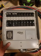
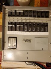
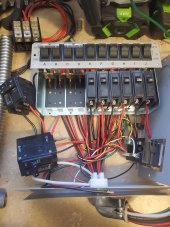
This week I entered phase 2 of my solar project (upgrade the breaker box with additional Breakers, interlock panel, and wire power room transfer panel to the breaker box)phase one (to complete my power room which is about 95% completed).
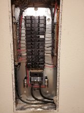
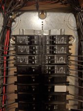
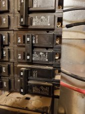
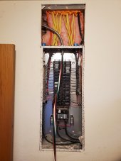
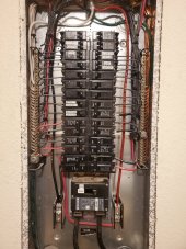
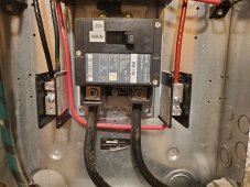
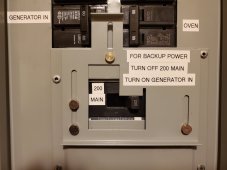
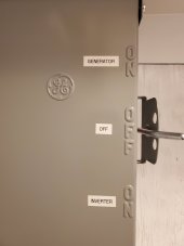
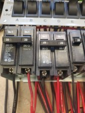
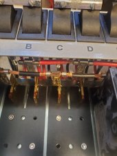
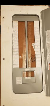
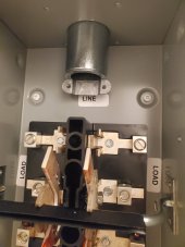
I started by removing the old breaker box cover and staring at this thing for a long time figuring out how to get the power into the box through the Attic in the least invasive way. Also at the start of this the old breaker box had three extra 120 spaces. I needed to add two new 240 Breakers. One 60 amp for the generator input and one 60 amp for power out.
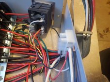
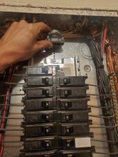
After going into the attic and staring at it there was so many wires coming out of the top of the breaker box into the Attic. As well as it appeared that I had a double plate(later turn out to be 3 2×4's thick)on that wall above the breaker box which further was going to make it more difficult.
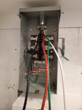
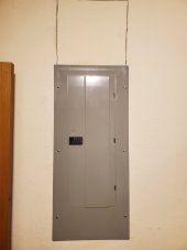
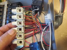
So I then decided I was going to have to come in next to the breaker box on the outside of that wall stud and bring it through the stud into the top of the breaker box as much as I hated to do it I cut panel of sheetrock out above the breaker box.
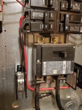
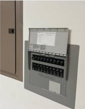
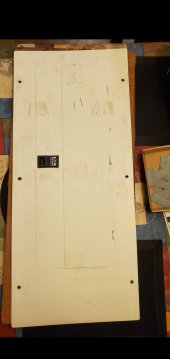
This also will allow me access to the top of the box one more time to run a 60 amp feed from the newly installed additional 240 breaker. It run through my attic to the side of my house which will later feed my garage and power my mother's air conditioners with the grid tie system once it's installed.
 

Attachments

  • Screenshot_20230409-105019_QuickPic.jpg
    Screenshot_20230409-105019_QuickPic.jpg
    245 KB · Views: 17
  • Screenshot_20230409-105002_QuickPic.jpg
    Screenshot_20230409-105002_QuickPic.jpg
    329.3 KB · Views: 16
  • 20230405_222955.jpg
    20230405_222955.jpg
    172.5 KB · Views: 17
  • 20230405_221340.jpg
    20230405_221340.jpg
    112.1 KB · Views: 17
Last edited:
I started out by adding split Breakers and condensing the breakers down to make room for the new 240 Breakers. I was able to install two split breakers on each side which made room for the 240 breakers. That left the three Extra Spaces which I then installed three more split Breakers allowing me six extra 120 circuits for later use.
After getting the breakers reconfigured and moved around( I put the 240 Breakers closest to the main ) I then installed two bus blocks. The blocks are going to allow multiple input/outputs. The power room will go to the busses then to generator input. The busses will allow a feed to an additional transfer panel( I had bought a pro Tran 10 circuit critical load sub panel that will be repurposed).
I then wired the buss blocks to the generator input.
 

Attachments

  • 20230406_214738.jpg
    20230406_214738.jpg
    199.1 KB · Views: 10
  • 20230406_214745.jpg
    20230406_214745.jpg
    171.8 KB · Views: 9
  • 20230406_214800.jpg
    20230406_214800.jpg
    156.4 KB · Views: 9
  • 20230406_214806.jpg
    20230406_214806.jpg
    156.5 KB · Views: 10
Last edited:
I then cut out the sheetrock above the breaker box drilled through the top plate left of the breaker box with a long spade bit. I then used an oscillating cutter and cut a square in the stud next to the sheetrock panel I had cut out to allow the 6/3 mc to pass through and into the top of the breaker box.
Next was the fun part my son and I climbed in the Attic got the the wiring down into the power room and I clamped the MC in the transfer panel in the power room. Then I went into the utility room and my son fed the MC through the top plate I was able to grab it pull it over through the stud wall and feed it into the breaker box and then attach it to the pass-through clamp. I had bought 25 ft of 6/3 MC. I was thinking I only needed 20 ft but I got extra 5 ft just because. Good thing I got 25 ft as I only ended up with about eight extra inches in the power room and maybe a foot extra in the utility room.
I then wired up both the utility room and the generator room powered on and took voltage readings at both rooms. The readings were great didn't even have a single volt of voltage drop.
 

Attachments

  • 20230408_202421.jpg
    20230408_202421.jpg
    96.9 KB · Views: 13
  • 20230408_195746.jpg
    20230408_195746.jpg
    142.6 KB · Views: 12
  • 20230408_212232.jpg
    20230408_212232.jpg
    146.3 KB · Views: 12
  • 20230408_210718.jpg
    20230408_210718.jpg
    225.9 KB · Views: 12
  • 20230408_210725.jpg
    20230408_210725.jpg
    247 KB · Views: 10
  • 20230408_212958.jpg
    20230408_212958.jpg
    119.2 KB · Views: 12
  • 20230408_212833.jpg
    20230408_212833.jpg
    191 KB · Views: 13
Last edited:
Everything wired up and looking great. Meter readings were perfect. I then put the cutout drywall back in temporarily using just a little silicone as I plan on later adding a feed from the breaker box to the other end of my house. I installed the new interlock breaker panel cover and spent what seemed like forever printing labels and putting them on the breakers. The end result I am happy with the the way it turned out. Now it's official I can have backup power at will flip a switch push a button throw a transfer lever yay team !! Lol.
Later today I plan on powering the backup system up and I'm going to load test the system. Will see how much a SW5548 can power in the house. I'm pretty sure it will support the whole house less the oven.
 

Attachments

  • 20230408_215346.jpg
    20230408_215346.jpg
    150.2 KB · Views: 13
  • 20230408_215406.jpg
    20230408_215406.jpg
    145.8 KB · Views: 13
  • 20230408_215449.jpg
    20230408_215449.jpg
    63.3 KB · Views: 13
Last edited:
.... I had bought 25 ft of 6/3 MC. I was thinking I only needed 20 ft but I got extra 5 ft just because. Good thing I got 25 ft as I only ended up with about eight extra inches in the power room and maybe a foot extra in the utility room.
...
Smart to have the extra. I always pad my wire run measurements with several additional feet. I would much rather cut off the not needed wire than find out I did not have quite enough to reach.
 
So I had mentioned earlier about the protran 10 circuit transfer switch I was originally going to use as a critical load panel. My system when it's complete will have two completely separate inverter systems. The main system will be a 12.5 KW Fronious Primo grid tied at the meter with 2 arrays at 15kw total.
The second system backing up the grid tie should it go down will be my power room (which feeds to the generator in breaker on my new interlock panel). It consists of two Zantrex Sw5548's powered by a 20.5kwh Iipo4 battery bank 10kw of solar(coming this summer hopefully) thru a Victron Rs 450/200, and will be backed up by a 10 KW propane, in the power room I can feed the interlock panel in the utility room from the inverters or the generator via a transfer switch in the power room.
So the way it's wired now it's going to be all of the grid tie system or all of the backup system which is great. But in my thinking it would be a shame to have 10 KW of solar just sitting there on backup because once the batteries are charged it will just sit there doing virtually nothing.
So I decided to repurpose the protran 10 circuit transfer panel and then rather than being critical load panel . I'm going to wire it in as grid tie system or backup system so I'm going to be able to run my air conditioner my well and six other circuits at will between grid tie and off grid so while I'm on grid tie system I will able to run the off grid system to those 10 circuits it's going to allow me to use both systems at the same time with out ever having the chance of either touching one another. I think it's a pretty good idea once again repurposing what I thought would be left over outdated equipment. I plan on flush mounting it to the left of my breaker box and I contacted protran about getting a lid for it as the new models have that way you can't see the breakers. It has a power meter so it will also show load and balance on the two legs separately.
 

Attachments

  • 20230406_225753.jpg
    20230406_225753.jpg
    165.9 KB · Views: 12
  • Screenshot_20230409-130621_Messages.jpg
    Screenshot_20230409-130621_Messages.jpg
    216.3 KB · Views: 12
  • 20230326_162116.jpg
    20230326_162116.jpg
    46.6 KB · Views: 12
Last edited:
Protran has this 10 circuit transfer box listed as a 50 amp critical load panel but I had read somewhere that the buss was only 10 gauge and thereby they were overrating this panel.
So I took apart this thing apart and sure enough the main buss is only 10 gauge and that would not be good for anything other than temporary use.
So as I plan on putting this into service for continuous duty it appears I'm going to have to upgrade this box. I have come up with a pretty good simple and cheap plan using leftovers once again. I'm going to upgrade the buss bar. I plan on feeding each 240 breaker with its own 10 gauge wire. I'm going to splice into this bus bar in two places the first 10 gauge feed that's already there I will allow to feed the first 30 amp breaker, the second 10 gauge feed I will add in between the 240 volt Breakers( the second which only had a 20 amp breaker, ordered a 30 to replace it) will feed my well.(which is now actually powered from the trailer I used to live in before I built my house at a later date love to show the transfer switch I built for my well it can be powered from the trailer or the house) I will add a third additional feed wire to the opposite end of the buss to feed the 120 Breakers. This buss bar will then have three legs of 10 gauge going to it. Additionally the second 240 breaker was rated at 20 with 12 gauge wiring I will replace with a 30 amp breaker and 10 gauge wiring to support it.
The backup power coming in goes to this little buss bar on the bottom of the protran unit I'm going to replace that with a buss bar of the exact same design with slightly larger inputs a 6 gauge will fit in this one and have some room whereas the factory install one you have to cram a 6 gauge into it so once that's replaced the three 10 gauge wires will easily fit into one of terminals and I will feed it with 6 gauge from the buss blocks in the breaker panel I just installed.
Love to hear thoughts about this upgrade and the use of the protran between the two inverter systems allowing both systems to operate together at the same time. Thanks GW
 

Attachments

  • 20230327_235243.jpg
    20230327_235243.jpg
    152.8 KB · Views: 11
  • 20230409_133316.jpg
    20230409_133316.jpg
    144.4 KB · Views: 11
  • 20230409_131719.jpg
    20230409_131719.jpg
    196.8 KB · Views: 13
  • 20230409_131721.jpg
    20230409_131721.jpg
    130.1 KB · Views: 13
  • 20230409_131746.jpg
    20230409_131746.jpg
    260.5 KB · Views: 13
  • 20230409_131751.jpg
    20230409_131751.jpg
    255.7 KB · Views: 11
Last edited:
Smart to have the extra. I always pad my wire run measurements with several additional feet. I would much rather cut off the not needed wire than find out I did not have quite enough to reach.
That's for sure I learned my lesson years ago. I had did electrical work and there's nothing worse than too short or you have to pull it tight to install it.
 
Back
Top