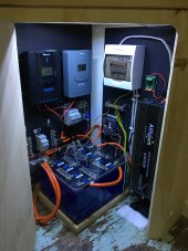
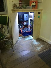
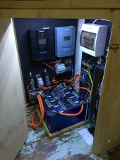
Finally put the finishing touches on my battery this weekend which I've discussed in various threads and had some great support/help from the community members here in planning. It's been functioning since around Christmas, but I've slowly been adding all the nice to haves.
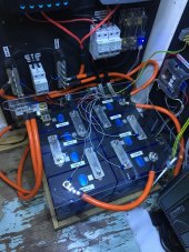
This weekend I added some beefier home-made busbars (from crushed copper pipe which I've tinned myself - I've outlined the process in detail in another thread) and a perspex cover over the cell terminals which were the finishing touches.
Key points of interest:
- The cells are 280Ah EVE cells from Basen. Total tested capacity of the pack from 3.6V down to 2.5V is a touch over 270Ah which I'm happy with for the price. The main reason I don't quite get full capacity is differing resistance between cells, meaning I get low voltage disconnect on one cell while a couple of others still have capacity remaining.
- My inverter is run straight off the battery rather than via the BMS due to the amperage rating of the BMS being too low. To protect against over-discharge, I cut the remote switch cable to my inverter and ran it via a low-voltage disconnect board (relay). The relay switch is then connected to the BMS - therefore once the BMS cuts the discharge the relay cuts and turns the inverter off. This is functioning great. I had a couple of members raise on here that some inverters may not like being switched off under load - my manual doesn't say anything about this and the inverter doesn't seem to mind. Aside from this consideration, this solution seems to be a great alternative to more expensive pro latch / battery protect type products.
- My inverter is a 4000W/8000W pure sine wave from a 4x4 company here in Aus. It works great and provides the rated power no worries, however in setting up the A/C system I realised the inverter is actually split phase (both L and N are 120V with respect to ground). This is apparently relatively common in inverters, however the manual doesn't say anything about it. Just a bit of a watch-it for others. Annoying for my as I now can't have neutral bonded to ground. I will make sure my next inverter has a true neutral.
Anyway - I just thought I'd put up some photos as a thanks to those who helped point me in the right direction on the build.


