diy solar

diy solar

Building A New 48 Volt System, Planning To Execution...

When You Can't Find What You Want On The Common Market... Make It.

Electromagnetic Induction Silver Soldering This Morning To Make Brass 3/8" Flange Bolts With 1" Contact Surface Area.
This Is Structural Silver Solder (Mostly Nickel) And Takes An O2 Enriched Torch To Do Normally,
But a dip in flux, a dip in 'Silver Solder Flakes' and into the induction coil, about 15 seconds and it's done.
Sure beats getting out the brazing torch and fiddling around with all that crap...

View attachment 6118

You might notice the Nylon clamp on the ferrite ring, the induction will heat the crap out of anything electrically conductive in close proximity, so Nylon or some kind of non-conductive stand-off between inductor and sheet metal handle/bracket.

View attachment 6119

I have to sneak up on timing, I can melt that bolt into slag with no problems whatsoever, so it takes a little experimentation to get it just right...

Ceramic Ferrite Ring,
Litz Wire,
High Temp Fiberglass Covering,
Induction Driver,
Power Supply,
All from eBay, about 2,500 Watts on this one for about $150.
Smaller ones on 12V power supply can reach about 1,000 Watts for around $60.
Abrasive ceramic saw blade to cut the gap in the ferrite ring, hardware store.


Silver Solder Paste, or Brass Brazing Paste on the parts, push the button, perfect brazed/soldered joints every time.


When I was working on moving the compressor for my fridge and installing the A/C, ect. I just knew there had to be a better way to braze all those line sets, and this is what I came up with.
The open ferrite means I can concentrate the electromagnetic energy on a closed line, right at the joint I'm soldering/brazing, and still get it off because it's not a closed coil like in the pictures below.

Makes things like this stupid simple.

A different application, same idea.

View attachment 6121View attachment 6122

This one has a hollow tube tube for an Inductor, when the unit is going to be powered for a prolonged period, the inductor has to be cooled, I simply run water or coolant through it.

I've built Drivers/Inductors large enough for my home pressure canners, no more heat & steam in the house during canning season, no more propane, the sun provides the energy.
I love the science of home pressure canning, and I'm dragging some 21st century science into an 19th century process.
Interestingly enough, the 19th century machines still do the best job, I haven't found a way to build a better can seamer (sealer) that were made in the late 19th, very early 20th century...
OK, is that an induction coil? If so is the intention of it for heating stuff like melting metal? If so what ferquency are you feeding to the coil and with how many watts? Forgive me if i'm not keeping up!
 
If you stop busting my chops about inductance, impedance, resistance and torquing...

I haven't broken out the torch for brazing or silver soldering in 15 years, Not since I discovered brazing & silver soldering paste and electromagnetic induction heating.
I did a LOT of copper tubing coolers for hydraulic lines in big production presses and other machines, LOTS of pressure in hydraulic lines...

View attachment 6143

I don't suggest using a bare inductor coil, too easy to short it out on the piece being heated.
The fiberglass wrap is hitting the easy button.

View attachment 6144

Those swaged tubing ends are a great place for paste or solder to sit.

View attachment 6145


I build my own, these are all over the internet surplus sites...

Keep in mind if out want to run the inductor for long periods, you will need tubing for cooling.
When it's a short time event that doesn't overheat the inductor a solid can be used, like the Lits wire on the ferrite ring above, and the solid copper wire can be used.
Did you take those photos?
 
OK, is that an induction coil? If so is the intention of it for heating stuff like melting metal? If so what ferquency are you feeding to the coil and with how many watts? Forgive me if i'm not keeping up!
Did you take those photos?

The first post pictures are my stuff, the second post is off the internet, commercial pictures for the HVAC guy.
 
Last edited:
Between all of Asia going on vacation, then getting sick, things are progressing slowly, but making some progress...

Had a successful panel string test, finally got reasonable sun on a 60ish degree day yesterday (raining again today :poop:) so it looks like everything is going to come in reasonably on the numbers, but I don't discount a screw-up or two to still happen considering who is doing it... :rolleyes::unsure:

YUP! Can't even get pictures to post correctly, let's try again...
At this rate, I'll need 2 fire extinguishers!

1580850778041.png

1580851029743.png

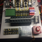
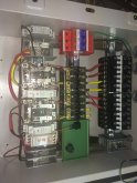
Held up by some terminals, a breaker, a voltage sensor, so other little bits & pieces...
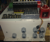
About time to start loading the box, need to get glands in the correct places... Mostly little stuff now.
 
Last edited:
A little progress, still waiting on some small parts...
Still haven't had ice yet so still wondering if the PWM will work for an Ice melt or not.

1581108577188.png

DIN rails really are 'Legos' for electrical nerds! :geek:
 
Last edited:
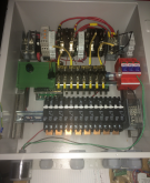
Getting some color coding on the wires as the correct wire/insulation comes in.
8 Ga, marine tinned copper conductor, 600V insulation, 40A terminals for what shouldn't run more than 30A...

Getting 8 Ga, tinned copper in colors other than the traditional AC colors (plain red, black, white & green) is more difficult than you think.

Red w/Black trace, Red w/Violet trace, Yellow, and Blue is on the way...
(Some time in the next two months hopefully).

IMG_1404.JPG

Small wires, Red & Black, 48v battery voltage, Purple diode wires.
Really small wires, switch to PWM ice melter hidden in back of case, but power switch & control knob need to be up front...
 
Last edited:
Back
Top