Hi everybody, I'm hoping somebody can point me in the right direction here, i'm a programmer and i have experience designing embedded circuits but I have 0 experience with solar panels or batteries so this is all new to me.
My goal is to have a fully solar powered landscape lighting system for my backyard, the system I'm building wouldn't need an inverter as it's all DC powered.
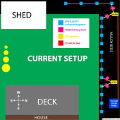
Currently I have this setup:
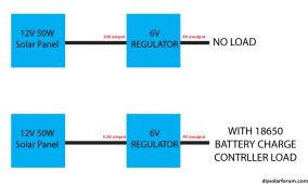
12V50W solar panel
14AWG low voltage landscape lighting wire running from solar panel across yard
6V regulators feeding from the solar panel line
boxes with 18650 batteries with charge controller/battery protection pcb feeding off the 6V regulator
4 spotlights per battery each running at 3.7V each drawing about 40mA average
This system works fine but:
#1 the batteries charge slowly and don't last that long
#2 the batteries charge at different rates depending on how close they are to the panel and lights turn off at different times
#3 the battery charge controllers only provide power to the lights when there's no solar input, this causes the lights to turn on about an hour before sunset when trees start blocking sunlight to the panel
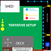
To improve this, I'm considering a centralized 12V LiFePO4 battery in my garage connected to the solar panel. This setup should address charging inconsistencies and synchronize light activation with an ESP32 and a relay. Alternatively, I'm exploring the simplicity of a portable solar generator like the Anker 521.
Does this plan seem effective, or am I overlooking anything?
My goal is to have a fully solar powered landscape lighting system for my backyard, the system I'm building wouldn't need an inverter as it's all DC powered.
Currently I have this setup:
12V50W solar panel
14AWG low voltage landscape lighting wire running from solar panel across yard
6V regulators feeding from the solar panel line
boxes with 18650 batteries with charge controller/battery protection pcb feeding off the 6V regulator
4 spotlights per battery each running at 3.7V each drawing about 40mA average
This system works fine but:
#1 the batteries charge slowly and don't last that long
#2 the batteries charge at different rates depending on how close they are to the panel and lights turn off at different times
#3 the battery charge controllers only provide power to the lights when there's no solar input, this causes the lights to turn on about an hour before sunset when trees start blocking sunlight to the panel
To improve this, I'm considering a centralized 12V LiFePO4 battery in my garage connected to the solar panel. This setup should address charging inconsistencies and synchronize light activation with an ESP32 and a relay. Alternatively, I'm exploring the simplicity of a portable solar generator like the Anker 521.
Does this plan seem effective, or am I overlooking anything?