Yes poor practice on my part as I didn’t want to uncompress to place them in parallel.???? join the bus bars to increase the length and no bolts seams to be a bad idea
never saw that done before.????


You are using an out of date browser. It may not display this or other websites correctly.
You should upgrade or use an alternative browser.
You should upgrade or use an alternative browser.
Bulges on side of cells during top balance
- Thread starter Gurusi
- Start date
400bird
Solar Wizard
Your graph does show the scale for voltage, how high is that spike?
Also, where on the parallel pack were the charge and sense leads connected?
Also, where on the parallel pack were the charge and sense leads connected?
I’ve seen horror stories on the forum before, and did everything I feel I could to prevent this. But this is the nature of DIY and saving money compared to consumer packs.I wish I had a positive piece of advice but this is way beyond my knowledge. I do want to thank you for sharing this post as I have 32 cells in my garage that I am unboxing this weekend and I now have additional reading to do as my plan was to top balance as you did. Seems I will likely need to do different
It still hurts after three days lol but I’m now starting to plan to rebuild with 10 additional cells.
Top balancing based on the forum looks to be very safe and I recommend asking questions.
The only reason I individually topped up and discharged my cells individually last year was because they were going in storage.
I then hooked them up recently and all seemed to be good but a little out of balance. As this worked without my cells bloating I would likely do the slow individual cell charge again as I can’t afford to make more mistakes.
Charge was at 3.25, Spike was around 3.45. Didn’t save the log as I was in a rush to discharge. The charging/sense leads were down on the most bloated cells pack 8 and 16Your graph does show the scale for voltage, how high is that spike?
Also, where on the parallel pack were the charge and sense leads connected?
Quattrohead
Solar Wizard
Holy shit you basically blanched your cells, man I am sorry that happened but I can see exactly how it occurred.
A few pictures and explanation should be added to the top balancing explanation that apparently is around here somewhere.
A few pictures and explanation should be added to the top balancing explanation that apparently is around here somewhere.
I would rather not be made a case of!Holy shit you basically blanched your cells, man I am sorry that happened but I can see exactly how it occurred.
A few pictures and explanation should be added to the top balancing explanation that apparently is around here somewhere.
it’s unclear to me as regard the exact cause. Perhaps because I didn’t bolt my extended bus bars together, maybe because the degree of SOC between the individual cells was too acute, maybe because I didn’t leave the pack in parallel for a period of time settling before charging, maybe a glitch with the charger.
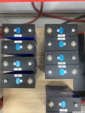
There is definitely less swelling the father away from the charge point. Cells 16,15,8 and 7 are packed up for recycling.
I’m unsure about packs 1,2,3,4 they have the least swelling as they were the furthest away. Cells 9-14 have no swelling
A flat pack of 4 cells is 11” 1/4 and the four swollen is 13”
I’m unsure about packs 1,2,3,4 they have the least swelling as they were the furthest away. Cells 9-14 have no swelling
A flat pack of 4 cells is 11” 1/4 and the four swollen is 13”
Attachments
Quattrohead
Solar Wizard
Were your voltage sense cables at the opposite end to the charging cables ?
That would have done it for sure with those poor connections between cells.
And I am not saying calling you out personally, just a couple of pictures and explanation of what can go wrong if the connections are not good.
That would have done it for sure with those poor connections between cells.
And I am not saying calling you out personally, just a couple of pictures and explanation of what can go wrong if the connections are not good.
Sensing cables were the next cell along.Were your voltage sense cables at the opposite end to the charging cables ?
That would have done it for sure with those poor connections between cells.
And I am not saying calling you out personally, just a couple of pictures and explanation of what can go wrong if the connections are not good.
I get it, just a joke as it is tough posting failures for all to see.
featherlite
Solar Enthusiast
Op, Say it ain't so!This. How are these bus bars connected??? Looks like heat shrink is the only thing bonding them together???
This. 0.05C cutoff for a 280Ah cell is 14 Amps, not 1 Amp.LiFePO4 “charged” status is a combination of voltage and current. ie: if you reach 3.65V at 0.05C current the cell is 100% charged. If you approach 3.65V at a lower current, or hold a lower voltage for a longer time, you can overcharge the cell.
Nobodybusiness
Collecting the leftovers of the Great Sky Reactor.
If you really wanted to do your busbars that way, I’m sure Weber would make ones long enough for you.Hey, just in the process of a 16S. 280ah top balance. Using the ZKEEBCA 40 L. They are Configured in parallel and a under compression.
I had previously been using the cells with the inverters but found imbalance at the higher range of 3.4v when charging via the charge controllers
I noticed a spike in voltage on the test software at about 3.35 V. And when examining the cells I noticed bulges in the first two cells so have stopped the balance. I’m unsure what the cause is or how I should proceed….
Have I done something wrong in the process? Is it too much compression?
Edit added better cell bulge photos
Otherwise probably not a good idea to use shrink wrap.
hwse
Solar Enthusiast
- Joined
- Jan 2, 2021
- Messages
- 585
You said "where my charger was hooked up." Does that mean that the + & - connections were both to the same cell? If so, given that you were charging with 40A, you likely had significant voltage drop from the charge end to the non-charge end. where did you have the voltage probes for the tester? if it was not in the first cell nearest the charge connection it if very likely that you went over the 3.65v on that cell.Underway discharging now. Charge settings were 3.65V C-CV, 40amps with a cutoff current of 1.amp.
I noticed the bulged end of the cells where my charger was hooked up was warm and noticeably cooler the other end.
Cells are compressed based on lots of reading on the forum and are variable for give (spring system). I can’t recall my spring in-lb settings right now!
I’m hoping I haven’t damaged them. but don’t know how to move forward. I could top balance each cell individually I guess
Similar threads
- Replies
- 9
- Views
- 602
- Replies
- 9
- Views
- 564
- Replies
- 3
- Views
- 230