diy solar

diy solar

Busbar help pls

Gould

New Member
Joined
Jan 18, 2021
Messages
306
Forgive what I’m sure is the umpteenth time this has been asked but I’m so back and forth I need some definitive guidance.

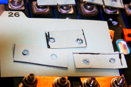
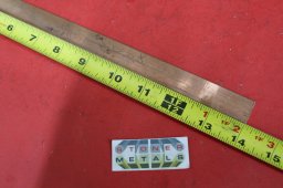
my cells came slightly bulged so I’m immediately cautious about the strain on the terminals. I started with 1/4” copper and making my own busbars. I wouldn’t call it a total loss but the length of my welded studs doesn’t leave enough grab for the bolts for my liking. Not to mention trying to line up the terminal holes is extremely challenging with the varying extent of bulge from cell to cell.

My next thought was making up some 4/0 jumpers. I just received the lugs this morning. This is the first time I’ve held them, wow they’re big! I’m sure I can make it work but seems like this will add a lot of bulk to the pack.

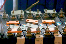
So I’m back on the fence. I’ll make up a couple of jumpers to test but also wondering if there is a source for heavier busbars that is recommended. The busbars that come with the cells don’t give me confidence.

Thanks!
 
You might want to consider some type of spacer system (holding the cells on the edges/corners) so the cells are not touching. That would take the load off of the terminals.
 
I will be applying some sort of compression, just not sure how extensive. I’m hoping a cycle or two while compressed will flatten them out.

just need to find a source for reliable busbars.
 
sticky cork on the corners and strap the cells together

onlinemetals.com and buy strips of copper and make your own

depending on your amps you can use strips of aluminum from the local hardware store
 
If this is just a series set up I would trust the bus bars that came with the battery.
How many amps is the BMS rated?
 
sticky cork on the corners and strap the cells together

onlinemetals.com and buy strips of copper and make your own

depending on your amps you can use strips of aluminum from the local hardware store
So am I stuck with the bulging? No chance they’ll flatten?
I’m using Overkill BMS’ so 120 amps max. I did take a stab at making my own busbars but creating the oblong hole is messy and aligning the holes with the posts is challenging because of the varying differences in bulge.
 
So am I stuck with the bulging? No chance they’ll flatten?
I’m using Overkill BMS’ so 120 amps max. I did take a stab at making my own busbars but creating the oblong hole is messy and aligning the holes with the posts is challenging because of the varying differences in bulge.
Using a press or by hand?
 
I think my plan is to add restriction, not compression to prevent further budging while I initially top balance. I only have 700w of converter so it’ll take a while but I’ll then run through a capacity test. My hope is they’ll flatten through this process. I’ll then apply e compression and top up again.
 
I too don't like the idea of compression to reduce the slight bulging; it doesn't seem like adding to the internal pressure can be helpful. My solution to the problem of securing the cells and allowing for a bit of movement because they are not firmly clamped, was to make jumpers from #2 fine strand welding wire and lugs. The cut wire lengths was 3-3/4 inch. They are bent into an arc before applying the second lug. The flex is sufficient enough to allow +/- 1/8" movement between cells without putting enough rotational force on the lugs to turn them on the terminal (probably more, but I only tested to +/- 1/8 inch). The #2 jumpers add a couple of millivolts to the voltage drop between cells, but in the overall scheme of things, that seems negligible.

I would have made the jumpers out of braided copper, the kind that was used to ground an engine or battery in cars back in the 30's and 40's but I didn't find a source for the copper braid. I'm sure it's out there though the #2 welding cable works fine.

I worry a bit about cells wearing through the blue plastic film outer sheath. The aluminum cans are connected to the negative terminal, so any damage to the blue plastic would result in a shorted cell. Hence my cells will sit in an aluminum frame box made from 1/8" thick aluminum, 1" angle and 1" bar, lined with 1/4" plywood. With fish paper sheets between the cells to backup the blue plastic film (or plastic kitchen cutting mat cut to shape; it's about 1/16" thick.

BTW, I also used 6mm SS Belleville washers to ensure a good long lasting clamp force on the terminals. The Belleville washers collapse fully at just under 14 NM of torque so are ideal. They recover to 80% of their original thickness when removed, so are doing a good clamping job. I found that SS lock washers did not do as well at ensuring a good clamp. I worry about aluminum cold flow over the long term (I worry about everything) though I will re-torque the studs every year or so.
 
Take a look at my recent post about making up some cardboard bus bars so that you can tweak out your alignments. I also posted the method I used and source to make custom bus bars from readily available inexpensive copper flat bar stock using simple hand tools.
 

Attachments

  • Paper busbars1.png
    Paper busbars1.png
    812.1 KB · Views: 17
  • Paper busbars2.png
    Paper busbars2.png
    870.5 KB · Views: 17
  • copper busbar stock.jpg
    copper busbar stock.jpg
    394 KB · Views: 17
Take a look at my recent post about making up some cardboard bus bars so that you can tweak out your alignments. I also posted the method I used and source to make custom bus bars from readily available inexpensive copper flat bar stock using simple hand tools.
How much current are you planning to carry? Those look awfully thick.

 
I am sure you are right. I was using this for a 8S 24v 100Ah battery pack I was building, and the copper flat bar was on hand. That is the only real reason I used it.

That thick copper was a PITA to cut and drill, hence my idea to make cardboard/cardstock busbar templates to verify alignments. I admit that I really didn't know what I exactly needed - and I probably would have been ok with some similar size aluminum flat bars instead. But I figured I couldn't go wrong with using thicker/wider copper than I needed. More is better.

I suspect I could have made out fine with aluminum of the same thickness, which I also had on hand - but I was just a newbie making my first LiFeP04 battery packs - which in the end turned out very, very well!
 
Last edited:
I too don't like the idea of compression to reduce the slight bulging; it doesn't seem like adding to the internal pressure can be helpful. My solution to the problem of securing the cells and allowing for a bit of movement because they are not firmly clamped, was to make jumpers from #2 fine strand welding wire and lugs. The cut wire lengths was 3-3/4 inch. They are bent into an arc before applying the second lug. The flex is sufficient enough to allow +/- 1/8" movement between cells without putting enough rotational force on the lugs to turn them on the terminal (probably more, but I only tested to +/- 1/8 inch). The #2 jumpers add a couple of millivolts to the voltage drop between cells, but in the overall scheme of things, that seems negligible.

I would have made the jumpers out of braided copper, the kind that was used to ground an engine or battery in cars back in the 30's and 40's but I didn't find a source for the copper braid. I'm sure it's out there though the #2 welding cable works fine.

I worry a bit about cells wearing through the blue plastic film outer sheath. The aluminum cans are connected to the negative terminal, so any damage to the blue plastic would result in a shorted cell. Hence my cells will sit in an aluminum frame box made from 1/8" thick aluminum, 1" angle and 1" bar, lined with 1/4" plywood. With fish paper sheets between the cells to backup the blue plastic film (or plastic kitchen cutting mat cut to shape; it's about 1/16" thick.

BTW, I also used 6mm SS Belleville washers to ensure a good long lasting clamp force on the terminals. The Belleville washers collapse fully at just under 14 NM of torque so are ideal. They recover to 80% of their original thickness when removed, so are doing a good clamping job. I found that SS lock washers did not do as well at ensuring a good clamp. I worry about aluminum cold flow over the long term (I worry about everything) though I will re-torque the studs every year or so.
CORRECTION: ..... Change that 14 NM to 4 NM. Also, after measuring voltage drop in the #2 welding cable at my max charge current (60 amps), I remade the jumpers with 1/0 welding cable. The #2 voltage drop was up around 5 mV. Not large in the overall scheme of things, but when the target balancing voltage is 20 or 30 mV, the extra few mV per cell (on only three of the four cells) bothered me.
 
I too don't like the idea of compression to reduce the slight bulging; it doesn't seem like adding to the internal pressure can be helpful.
If the batteries have returned to normal conditions internally they may not suck back in. We only live at 16 psi. Don't crank on it but I see no reason to not put normal compression on.
 
Back
Top