diy solar

diy solar

Can a Victron battery protect be used on the charge side of things or is it only for disconnecting loads?

Status
Not open for further replies.

Dzl

Unofficial Forum Librarian & Perpetual Newbie
Staff member
Moderator
Joined
Dec 10, 2019
Messages
5,108
Location
West of the rockies
Can a Victron battery protect be used on the charge side of things or is it only meant to be used for disconnecting loads?

And on a related note why is it not reccomended to use with an inverter? It seems that this sort of defeats its purpose of the battery protect as the inverter can be one of the biggest loads on some systems.
 
It *Can* be used in both cases, between charger & batteries,
Another one between batteries & inverter.

The issue is, most reasonable charge controllers have a high voltage limiter you can program.
No need for a disconnect between charger and batteries unless you expect a dead short at the batteries and want added protection, but it won't save the batteries.

A low voltage cut off between batteries & inverter is actually a good idea if your batteries don't have some kind of disconnect built in.
Make sure it's a MANUAL RESET!
You don't want an automatic reset, if the voltage drops, the batteries disconnect before being sucked low enough to damage them,
BUT,
Batteries can 'Rebound' once Load is off them, and an automatic reset will allow the Load to immediately kick the battery protection back on, over & over in a cycle...

Opening and closing a circuit with big amps through it can damage the electronics, and some batteries.
A manual reset makes you look for the Load, remove it before resetting so you can stay connected.

My inverter will draw lead acid batteries down, I'm trading battery longevity for some added Load time, but eventually the inverter will do the low voltage kick off I have to manually reset.

That low voltage kick off protection is WAY lower than what damages my LFP batteries, so I use a programmable low voltage cut off to protect expensive batteries that will be forever damaged if I rely on the inverter low voltage kick off.

I'd rather snap the inverter off when the batteries cut off, risking inverter damage than damage the much more expensive batteries.
 
It *Can* be used in both cases, between charger & batteries,
Another one between batteries & inverter.

The issue is, most reasonable charge controllers have a high voltage limiter you can program.
No need for a disconnect between charger and batteries unless you expect a dead short at the batteries and want added protection, but it won't save the batteries.

My thinking was that it might be possible to connect the remote terminals on the Battery Connect to a BMS, so it disconnects the charging sources based on whatever conditions (high voltage, low temp, high temp) the BMS deems it necessary to cutoff charging.

A low voltage cut off between batteries & inverter is actually a good idea if your batteries don't have some kind of disconnect built in.
Make sure it's a MANUAL RESET!
You don't want an automatic reset, if the voltage drops, the batteries disconnect before being sucked low enough to damage them,
BUT,
Batteries can 'Rebound' once Load is off them, and an automatic reset will allow the Load to immediately kick the battery protection back on, over & over in a cycle...

Yeah I would ideally like to have a cutoff between the battery and all loads, especially the inverter. Do you have a reccomendation for something that accomplishes that safely?
 
My thinking was that it might be possible to connect the remote terminals on the Battery Connect to a BMS, so it disconnects the charging sources based on whatever conditions (high voltage, low temp, high temp) the BMS deems it necessary to cutoff charging.

Now see, that's why I like this forum!
I never thought of that for a second, I mean the idea never crossed my mind.

What you are talking about is command, not programmed, the BMS protections command/control the switch.
That's actually a really GOOD idea!
If for no other reason redundancy in protection...

OK, can you hear the 'Crazy' grinding gears on this end? ;)


Yeah I would ideally like to have a cutoff between the battery and all loads, especially the inverter. Do you have a reccomendation for something that accomplishes that safely?

I have a Vectron BP220 on the way, and it has a BMS input on it.
I can't swear the smaller BP100 amp versions have the same thing, but the control connectors are identical.
I skipped right over the BMS part but since you asked I had a look at the data specs since I have them downloaded before I bought it.

I was going to use a programmable low voltage alarm to trigger it, what I'm doing now with a solenoid and latching relay.
This thing uses MOSFETs instead of breaker points that like to weld shut when voltage drops, and I shouldn't have to use capacitors to keep line differential under control so it doesn't arc and weld.

If I can plug it directly into BMS, problem solved!
Same on the over voltage side of things too!
You had one smokin idea, the MOST it would take is a latching relay since the Vecteon has instant open command capability!

The little version is like $35, the 220 amp version is like $95.
 
  • Like
Reactions: Dzl
not sure if this matters but from Victron's website "The BatteryProtect is not designed for reverse currents from charging sources. "

Im not sure why having the power outgoing from a solar panel is any different than outgoing from a battery. But then brochure says

"Note: the BatteryProtect can also be used as a charge interrupter in between a battery charger and a Li-ion battery. See connection diagram in the manual."
 
I think that's the BMS connection they were talking about, commanded instead of the automatic function, but I don't know for sure...
 
Yers its confusing Im running 200 Volts DC so 'Im interested in a solution to remotely cut off panels as well

I've been looking into solid state relays "opto contactors" a little bit lately, iirc some of them are rated for pretty high voltage DC on one side. That might be an option.
 
I also worry about PV voltage wont in most cases it be higher than 24 Volts

I was intending to put it on the 'downstream' side of the charge controller so it would be 24v
 
Yers its confusing Im running 200 Volts DC so 'Im interested in a solution to remotely cut off panels as well

What's the amp potential @ 200 volts?

This is where some 'Monkey' engineering comes in,
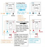
Voltage sensor, or command from BMS---> Latching Relay---> NC Relay.
Power relay that opens, held open with battery voltage until manually reset by latching relay.

Latching relays are like $5 on eBay, low amp 200+ volt relays are common,
The signal generator is the issue,
BMS would be perfect, but a high/over volts on the battery terminals or battery line would work, it's just not going to be in the mili-volt range..

Use a double latching relay boards and wire both together, a logic gate, both relays have to agree or the power relay doesn't close, that will give you manual control even with line noise.
(which there shouldn't be with battery supplied DC power, but it's also board failure redundancy or second input redundancy. Might as well get the most from your $5).
 
Latching relays stay in the state you put them in,
It takes a power pulse, then an 'Off', then back to powered to change the state, open and close the contacts inside.
They change state (open to closed, or closed to open) and stay there until an 'Off' cycle happens, and a second power pulse gets to them.

For instance,
A 'Beeper' won't work, just keeps switching the latching relay On/Off.
BUT,
A continuous light that just goes off when the problem corrects itself WILL work, without the second 'On' pulse the latching relay will stay in state without a second power pulse.

The light coming 'On', and staying on is one continuous power pulse, and when the light goes 'Off', it just completes the first cycle pulse cycle, and it takes a second power pulse to change the state of the relay to make it go back to where it was before the first 'On/Off' pulse cycle.
That would be you pushing the manual cycle button built onto the board with the little $5 units.

LatchingRelay2.jpg

While I didn't draw in the battery, the battery supplies the power to activate the relays, while the panels are independent circuits.
I also didn't draw in the signal generator, BMS, Over Voltage or Under Voltage sensors, etc because the signal generator can be anything, from an over or under volt light on the charge controller to a smoke detector/fire alarm, the latching relay doesn't care where the signal power comes from.

At my house, the main disconnect relays are wired to a latching relay, which in turn are wired to the smoke detector.
A second over temp sensor set at 110*F turns on the sprinklers, the two interlock.
Smoke everything gets shut down with exception of the protection system, and 110*F AND the smoke detector going off, the sprinklers go off.
I'm earth sheltered, and if there is smoke AND the temp ever gets above about 80*F there IS a fire!
My well water pressure tanks hold about 300 gallons, which will be sprinkled on the now disconnected power power equipment, the only thing running will be protection system connected directly to batteries.
(FLOOR DRAIN RECOMMENDED!)

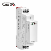
*IF* you have stepped fully into the 20th century and have DIN rail boxes,
This will give you the idea, but I'm NOT saying this will work for your particular application.
*IF* it were me, I'd use a separate relay for panel Positive & Negative strings, this will stop the differential problem and stop any arc over in it's track over using a Double Pole relay for Positive & Negative.
The Latching relay can easily handle two separate power relays.

https://www.ebay.com/itm/GEYA-Memor...hash=item1a58c769d9:m:mb_GyIzOiMt7acMormjowag

1578605099785.png

This is 6 Channels of latching relays ganged (6 isolated panel strings through power relays) for $12

https://www.ebay.com/itm/6-Channel-12V-Latching-Relay-Module-Switch-Controls-the-High-Voltage-H-Current/133264217588?_trkparms=aid=555018&algo=PL.SIM&ao=1&asc=20131003132420&meid=a39b033b17234fd091218c92713db677&pid=100005&rk=1&rkt=12&mehot=co&sd=121951095953&itm=133264217588&pmt=1&noa=0&pg=2047675&_trksid=p2047675.c100005.m1851

s-l500.jpg


Single Channel for $3


s-l1600.jpg


---------------------------

PERSONAL 'OPINION'/CHOICE WARING.

I STRONGLY DISLIKE 'Computer Controlled' or 'Digital' anything in safety systems.

I've had my go-arounds with Transient RF & EM signals (line switching noise in particular, running motors and circuits opening/closing) and I went with hard wired, ANALOG protection on a dedicated circuit.
With a water valve in the sprinkler line, I can cut the water to the sprinkler solenoid and test any part of the system without an umbrella and water damage...

YOU do what you think is best for you. Some people want to use the integrated home management systems ('Smart' Homes), that's their choice.
I started with a 'Home Protection Kit' that backup battery on the board I didn't know existed triggered the sprinklers...
I no longer have a 'Home Protection Kit', I beat it off the wall with a hammer.
Dark House, flooded room, and that 'Low Batt' light, 'Security, & 'Fire' red lights that normally indicated the fire/window/door alarm sensors still on, I SNAPPED...
 
Last edited:
  • Like
Reactions: Dzl
@JeepHammer Very important to note: A Victron BatteryProtect canNOT be used to disconnect the main DC line feeding an inverter... this has been covered to exhaustion on this forum, and is reflected in the updated user manuals available online from Victron. The only manufacturer-supported way to do this (read: the only way that doesn't void your warranty) is to use the BP to trigger the remote on/off of the inverter if so equipped.

The BP can be used to disconnect a charge source if the BP is connected in reverse - that is, with the charge source connected to the "in" post and the battery connected to the "out" post. Given that the BP is unidirectional in operation, any current from Out to In must not be permitted under any circumstances - this is what's meant by "reverse current". Current MUST NOT flow from "out" to "in". Failure to ensure this can result in a very high danger of fire or external component damage.

Actually, I have the spec sheet in front of me, having downloaded it before I purchased for low voltage cut off, and it contradicts itself, saying it can be externally controlled as a switch.
*I* (personally) would ask the manufacturer if manual control was possible, and IF SO, under what circumstances...
That's the same line that Craig pointed out, in my spec sheet/manual .pdf also, and from the manufacturer had you read the thread and watched this evolve...

(Laid out by Craig in post #5)

Personally, I buy very few 'Gadgets' that I can't control.
The reason I use over/under voltage/amperage alerts (which BMS is now on the radar! Thanks DZL!) through latching/amplifying relays and just open the circuit, Panels to Charge Controller, Charge Controller to Batteries, etc.

Since DZL dropped a HUGE idea on me in post #3, Using the BMS to control the Battery Cut Off MANUALLY between charge controller and battery...
(Or in my case control the power relays that are already there)
And since the spec sheet says there IS a possibility to do just that with LFP batteries, I'm going to explore it with the manufacture instead of taking something written on a forum as 'Mandate From On High' from internet users that are NOT the manufacturer.

NOT being a newbie to this, and being able to build this stuff from common (And inexpensive) pieces/parts,
AND being able to design sub-systems for a modular integrated system, that fits my REQUIREMENTS SPECIFICALLY,
I'm a MODULAR component guy, I don't care for 'Combined' gadgets that can't have specific component/circuits replaced or changed for my evolving system.

The 'General Warnings' laid down by the manufacturer for 'Bubba Thumbuster' or 'Never Did This Before DIY Guy' don't apply to me since I'm building something specific, not throwing together 'Gadgets' and hoping it solves some issue I don't understand and need 'Rescued' from myself...

Now, if we can get back to Craig's issues...
 
I was intending to put it on the 'downstream' side of the charge controller so it would be 24v

Latching relays stay in the state you put them in,
It takes a power pulse, then an 'Off', then back to powered to change the state, open and close the contacts inside.
They change state (open to closed, or closed to open) and stay there until an 'Off' cycle happens, and a second power pulse gets to them.

For instance,
A 'Beeper' won't work, just keeps switching the latching relay On/Off.
BUT,
A continuous light that just goes off when the problem corrects itself WILL work, without the second 'On' pulse the latching relay will stay in state without a second power pulse.

The light coming 'On', and staying on is one continuous power pulse, and when the light goes 'Off', it just completes the first cycle pulse cycle, and it takes a second power pulse to change the state of the relay to make it go back to where it was before the first 'On/Off' pulse cycle.
That would be you pushing the manual cycle button built onto the board with the little $5 units.

View attachment 4811

While I didn't draw in the battery, the battery supplies the power to activate the relays, while the panels are independent circuits.
I also didn't draw in the signal generator, BMS, Over Voltage or Under Voltage sensors, etc because the signal generator can be anything, from an over or under volt light on the charge controller to a smoke detector/fire alarm, the latching relay doesn't care where the signal power comes from.

At my house, the main disconnect relays are wired to a latching relay, which in turn are wired to the smoke detector.
A second over temp sensor set at 110*F turns on the sprinklers, the two interlock.
Smoke everything gets shut down with exception of the protection system, and 110*F AND the smoke detector going off, the sprinklers go off.
I'm earth sheltered, and if there is smoke AND the temp ever gets above about 80*F there IS a fire!
My well water pressure tanks hold about 300 gallons, which will be sprinkled on the now disconnected power power equipment, the only thing running will be protection system connected directly to batteries.
(FLOOR DRAIN RECOMMENDED!)

*IF* you have stepped fully into the 20th century and have DIN rail boxes,
This will give you the idea, but I'm NOT saying this will work for your particular application.
*IF* it were me, I'd use a separate relay for panel Positive & Negative strings, this will stop the differential problem and stop any arc over in it's track over using a Double Pole relay for Positive & Negative.
The Latching relay can easily handle two separate power relays.

https://www.ebay.com/itm/GEYA-Memor...hash=item1a58c769d9:m:mb_GyIzOiMt7acMormjowag

View attachment 4812

This is 6 Channels of latching relays ganged (6 isolated panel strings through power relays) for $12

https://www.ebay.com/itm/6-Channel-12V-Latching-Relay-Module-Switch-Controls-the-High-Voltage-H-Current/133264217588?_trkparms=aid=555018&algo=PL.SIM&ao=1&asc=20131003132420&meid=a39b033b17234fd091218c92713db677&pid=100005&rk=1&rkt=12&mehot=co&sd=121951095953&itm=133264217588&pmt=1&noa=0&pg=2047675&_trksid=p2047675.c100005.m1851

s-l500.jpg


Single Channel for $3


s-l1600.jpg


---------------------------

PERSONAL 'OPINION'/CHOICE WARING.

I STRONGLY DISLIKE 'Computer Controlled' or 'Digital' anything in safety systems.

I've had my go-arounds with Transient RF & EM signals (line switching noise in particular, running motors and circuits opening/closing) and I went with hard wired, ANALOG protection on a dedicated circuit.
With a water valve in the sprinkler line, I can cut the water to the sprinkler solenoid and test any part of the system without an umbrella and water damage...

YOU do what you think is best for you. Some people want to use the integrated home management systems ('Smart' Homes), that's their choice.
I started with a 'Home Protection Kit' that backup battery on the board I didn't know existed triggered the sprinklers...
I no longer have a 'Home Protection Kit', I beat it off the wall with a hammer.
Dark House, flooded room, and that 'Low Batt' light, 'Security, & 'Fire' red lights that normally indicated the fire/window/door alarm sensors still on, I SNAPPED...
Thanks I have been looking at the din rail relays Iike these was wondering if one on each side would be good.
 
LOL @JeepHammer Okay... don't listen to the registered Victron Product Expert, moderator on the Victron Technical Support Community, personal friend of Matthijs, and actual distributor of Victron equipment. Have at it, buddy (y)
 
Actually, I have the spec sheet in front of me, having downloaded it before I purchased for low voltage cut off, and it contradicts itself, saying it can be externally controlled as a switch.
*I* (personally) would ask the manufacturer if manual control was possible, and IF SO, under what circumstances...
That's the same line that Craig pointed out, in my spec sheet/manual .pdf also, and from the manufacturer had you read the thread and watched this evolve...

(Laid out by Craig in post #5)

Personally, I buy very few 'Gadgets' that I can't control.
The reason I use over/under voltage/amperage alerts (which BMS is now on the radar! Thanks DZL!) through latching/amplifying relays and just open the circuit, Panels to Charge Controller, Charge Controller to Batteries, etc.

Since DZL dropped a HUGE idea on me in post #3, Using the BMS to control the Battery Cut Off MANUALLY between charge controller and battery...
(Or in my case control the power relays that are already there)
And since the spec sheet says there IS a possibility to do just that with LFP batteries, I'm going to explore it with the manufacture instead of taking something written on a forum as 'Mandate From On High' from internet users that are NOT the manufacturer.

NOT being a newbie to this, and being able to build this stuff from common (And inexpensive) pieces/parts,
AND being able to design sub-systems for a modular integrated system, that fits my REQUIREMENTS SPECIFICALLY,
I'm a MODULAR component guy, I don't care for 'Combined' gadgets that can't have specific component/circuits replaced or changed for my evolving system.

The 'General Warnings' laid down by the manufacturer for 'Bubba Thumbuster' or 'Never Did This Before DIY Guy' don't apply to me since I'm building something specific, not throwing together 'Gadgets' and hoping it solves some issue I don't understand and need 'Rescued' from myself...

Now, if we can get back to Craig's issues...
Maybe fair enough for yourself Jeephammer, but bearing in mind lots of 'Never Did This Before DIY Guy' , like myself, read many of these posts and any extra warnings are well recieved. Easy enough for you with your experience to just ignore and do your own thing, but for the rest of us mortals....it makes us think just a tad more.
 
LOL @JeepHammer Okay... don't listen to the registered Victron Product Expert, moderator on the Victron Technical Support Community, personal friend of Matthijs, and actual distributor of Victron equipment. Have at it, buddy (y)

I hope you got that out of your system... Apparently we AREN'T being allowed to continue with the discussion/evolution of an idea...

And NO, I don't often listen to salesmen/installers because they aren't the manufacturer.
They know what they have been taught, not what everything is capable of, that's why 'Contact Manufacturer Tech' lines are available...

Unless YOU designed the unit from scratch, I'll ask the manufacturer, as I stated before when attempting to use it for 'Other Than Designed Application'.
Thanks anyway.

---------------------------

Thanks I have been looking at the din rail relays Iike these was wondering if one on each side would be good.

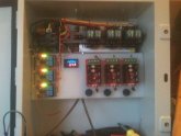
I push the 'Easy Button' whenever I can, so I usually mount things like the little PWMs, Latching Relays, Little Buck voltage converter boards on something NON conductive.
HDPE is dirt cheap for example, but if you need something specifically sized or shaped, you can buy Phenolic Resin powder and cast your own. I do this around strange shaped High Amp terminals and such...

Then it's up to the DIN rail for full power switching... But this is almost obsolete with DIN units doing both the Latching & High Power relay work.

image_zpsewbwkiqu.jpg
 
I hope you got that out of your system... Apparently we AREN'T being allowed to continue with the discussion/evolution of an idea...

And NO, I don't often listen to salesmen/installers because they aren't the manufacturer.
They know what they have been taught, not what everything is capable of, that's why 'Contact Manufacturer Tech' lines are available...

Unless YOU designed the unit from scratch, I'll ask the manufacturer, as I stated before when attempting to use it for 'Other Than Designed Application'.
Thanks anyway.

---------------------------


I push the 'Easy Button' whenever I can, so I usually mount things like the little PWMs, Latching Relays, Little Buck voltage converter boards on something NON conductive.
HDPE is dirt cheap for example, but if you need something specifically sized or shaped, you can buy Phenolic Resin powder and cast your own. I do this around strange shaped High Amp terminals and such...

Then it's up to the DIN rail for full power switching... But this is almost obsolete with DIN units doing both the Latching & High Power relay work.

View attachment 4813
Looks nice and yes I'm a fan of hdpe. Need to check out the resin though as I was looking just last night for custom non conductive boxes for a battery I'm designing.
 
Maybe fair enough for yourself Jeephammer, but bearing in mind lots of 'Never Did This Before DIY Guy' , like myself, read many of these posts and any extra warnings are well recieved. Easy enough for you with your experience to just ignore and do your own thing, but for the rest of us mortals....it makes us think just a tad more.

Jim, no offense intended, Craig & I pointed out the actual instructions say there is a way to manually control the voltage switch.
Were were kicking around an IDEA, not selling it as fact, just exploring an option that is apparently available as per the manufacture's instructions.

It's the 'Word Of God' post that IGNORED the manufacturer's instructions this unit *Might* be able to do the job we were discussing between charge controller and batteries, and noting that clarification from manufacture (not random internet guy) was the way to find out *IF* and exactly how to use the disconnect in that position.

Then the 'Random Internet Guy' doubled down on the oversight about POSSIBILITIES and declared himself the absolute authority, despite the manufacturers writing that this may be possible.

No one was trying to sell it as a 'MUST DO', just exploring options that *Might* be possible per manufacturers spec sheet.

'DIY GUY' is NOT an insult, everyone learns someplace, and like in this thread, some interesting ideas just popped up I didn't connect the dots on,
But if DZL's idea is compatible with an Off The Shelf device, this might be HUGE for LFP battery protection!
 
Status
Not open for further replies.
Back
Top