diy solar

diy solar

CAN and RS485 BMS Interface with multiple emulated Inverter protocols for JkBms Jbd BMS Daly 123Smart

i have a question/discussion

So we should see current flow like water, right?
Water always finds its level
So storage charges should also find their level right?

Should this not mean if we have say for example a battery level to say 90%
and then we have another that is 50%
if we connect them in parallel current should flow from the 90 to the 50 to level it up

Let's call it Passive sleep mode balancing...if that's correct


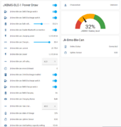
View attachment 197079

Then why can't we have the above??

Just a simplified thought - don't bite me :)

# Question is mainly to the developers who already know some Maths to this

# and to any other technical-minded person out there on these kind of projects

Note: this is a High-Level Design.
in more detail, the Batt 2 wires actually connect to the Batt 1 before the BMS terminals....
I would install a breaker switch between them.
 
Hi,

looks nice currently have succeeded with another project but single battery

would this work for Solis 3kw hybrid inverter so i can connect 2 batteries through JK2A24s15P bms in parallel?

second question - would this work with the SP2000 Growatt controller?


regards
jkbms will work


sp200 controiller no
 
i have a question/discussion

So we should see current flow like water, right?
Water always finds its level
So storage charges should also find their level right?

Should this not mean if we have say for example a battery level to say 90%
and then we have another that is 50%
if we connect them in parallel current should flow from the 90 to the 50 to level it up

Let's call it Passive sleep mode balancing...if that's correct


View attachment 197079

Then why can't we have the above??

Just a simplified thought - don't bite me :)

# Question is mainly to the developers who already know some Maths to this

# and to any other technical-minded person out there on these kind of projects

Note: this is a High-Level Design.
in more detail, the Batt 2 wires actually connect to the Batt 1 before the BMS terminals....
I would install a breaker switch between them.
i am not Shure what u mean!

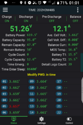
If u have more battery packs in parallel all packs will have same voltage on enads so in theory is same SOC, but if u have a cell on 3.5 and rest are on 4 V the pack is not 90 % because the cell from 3.5V will discharge to protection faster!

so in the end when use parallel packs u need to send to invertor CVL DVL CCL DCL and SOC as one battery
I have all the modules but not sure of the connections right now, can you help?

i have this working on another project but, now i want to connect more than 1 battery.

otherwise, i will end up just balancing them and paralleling them making just one talk to the inverter without the CVL DVL CCL DCL and SOC

Thes are controlled by the JKBMS anyway...

whats your thoughts?
 
Last edited:
I have all the modules but not sure of the connections right now, can you help?

i have this working on another project but, now i want to connect more than 1 battery.

otherwise, i will end up just balancing them and paralleling them making just one talk to the inverter without the CVL DVL CCL DCL and SOC

Thes are controlled by the JKBMS anyway...

whats your thoughts?


CVL DVL CCL DCL and SOC are the data send to invertor by bms to work

CVL - Charge voltage level
DVL - discgarge voltage level
CCL - charge curent level
DCL - discharge curent level

u can send only from on jk bms to invertor but will not have the real amp readings , also change the charge curent and discharge current as manual to be like ur pack.
 
Because of lot of project i support in same time i need to make some management of projects, is hard to me to re take all conversation from forum for each of u, and some contact me in viber or whatup or telegram and in this moment is a big mess with lot of info.
Sorry for that i try to give my time to every one i can.
I will ad in Gdrive a folder for each with setups, hardware, invertors, and an project status.
And also i think i respond to same people to tow different forums.

the identifier will be form nick name. if u are not there just remaind me:

1 - Battery Hardare Setup
2 - Invertor protocol u need
3 - status of ur project
4 - we talk on whatup / viber / telegram before


will be online this week from 1 - 8 march , best for all
and some contact me in viber or whatup or telegram and in this moment is a big mess with lot of info.

Lool...you made me laugh when I read this line....don't worry at all I completely understand that you guys are busy
I count myself lucky when I get a reply from anyone of you project leaders.

I was just informed of the solution you have already in place where one can have 2 CAN ports - I was just about to start searching for that information and develop on it.


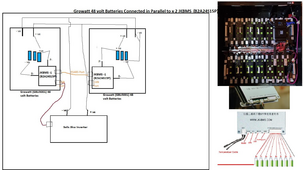
1 - Battery Hardare Setup - Solis inverter connected to 2 batteries (solution is supposed to look like the below diagram, but i didn't know how to get the 2 JKBMS.s to talk so i have omitted the RS485 communication for now of which its working but i don't trust it)

2 - Invertor protocol u need - i am using Pylontech protocol, i do not mind other protocols as long as its one that is listed in the Solis inverter options

3 - status of ur project - I would say 95 % completed , - not sure if the GPIO will change if i find your solution which would mean reflashing of the ESP32 chips

4 - we talk on whatup / viber / telegram before - i don't mind if we can talk on WhatsApp or Discord that would be great

My objective

1709317820582.png
 
Because of lot of project i support in same time i need to make some management of projects, is hard to me to re take all conversation from forum for each of u, and some contact me in viber or whatup or telegram and in this moment is a big mess with lot of info.
Sorry for that i try to give my time to every one i can.
I will ad in Gdrive a folder for each with setups, hardware, invertors, and an project status.
And also i think i respond to same people to tow different forums.

the identifier will be form nick name. if u are not there just remaind me:

1 - Battery Hardare Setup
2 - Invertor protocol u need
3 - status of ur project
4 - we talk on whatup / viber / telegram before


will be online this week from 1 - 8 march , best for all
and i think you should open a discord channel - that way all comms is live and there and other users can help other users on your behalf that should lighten the load...
 
Because of lot of project i support in same time i need to make some management of projects, is hard to me to re take all conversation from forum for each of u, and some contact me in viber or whatup or telegram and in this moment is a big mess with lot of info.
Sorry for that i try to give my time to every one i can.
I will ad in Gdrive a folder for each with setups, hardware, invertors, and an project status.
And also i think i respond to same people to tow different forums.

the identifier will be form nick name. if u are not there just remaind me:

1 - Battery Hardare Setup
2 - Invertor protocol u need
3 - status of ur project
4 - we talk on whatup / viber / telegram before


will be online this week from 1 - 8 march , best for all
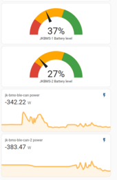
Right now - with the current setup - there is a 10% difference between both battery SOC while discharging

1709318848433.png
 
I gat to say this.

This is a Beautiful project...I mean we are taking this to a different level better than out-of-the-box manufactural specifications for the professionally released components :)

The functionality available to us are becoming way more advanced than the original product itself.

You guys are amazing.....
 
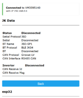
Looking for some help getting this up and running on my system. I have tried to connect with my JBD BMS on the NODEMCU serial (pins TXD, RXD), and Growatt LV on RS485 (D16, D17). On the web interface for JkBMS it says disconnected on both connections (see screen shot, and there is no actiity on the JBD BMS LED) so I am not sure if I have connected to the correct serial ports on NodeMCU chip. I am using the code JK_BMS_BLE_SERIAL_V4.2.partitions @0x8000, JK_BMS_BLE_SERIAL_V4.2.bootloader @0x1000
JK_BMS_BLE_SERIAL_V4.3 @0x10000.

JkBMS v2.0.15-rc.1 ; Arduino 2.0.9 ; Build Date Sep 11 2023 22:28:48

1709477443501.png

I read in a post about connection on serial 1 & 2, but the chip only has a hardware serial 0 and 1 (serial 2 is only TX) which is a bit confusing. Does it have SoftwareSerial on some other pins for JBD?

I have linked out the JDB on both SERIAL0 & SERIAL1 swapping the connection in case I had TX and RX the wrong way and it still does not work. I also tried the same on the JST connector from the original wiring diagram on pins D21 & D22, but it didn't work either.
Same goes for pins D19&D18 which seemed to be wired out to a terminal block on the wiring diagram, again didn't work.

I know the JBD port works as I have a butchered some arduino code to convert the JBD serial to pylontech CAN and I can use the serial monitor on Arduino software to see the values as text.

I also tried the blue tooth connection setting with the JBD BMS too but it does not connect on that either, for blue tooth do I need a seperate BT module connected to the NodeMCU or does it use the onboard one?

Thanks
 
thanks for the key, the data in coming to my esp, but my inverter only support UZE (UZ Energy) and WST (WS Technicals) protocol, can you please add UZE or WST support ?
checked with SRNE, they said I can use UZE if the battery support PLY protocol. now the battery and the inverter can communicate directly. thanks for your amazing work.
 
Lool...you made me laugh when I read this line....don't worry at all I completely understand that you guys are busy
I count myself lucky when I get a reply from anyone of you project leaders.

I was just informed of the solution you have already in place where one can have 2 CAN ports - I was just about to start searching for that information and develop on it.


1 - Battery Hardare Setup - Solis inverter connected to 2 batteries (solution is supposed to look like the below diagram, but i didn't know how to get the 2 JKBMS.s to talk so i have omitted the RS485 communication for now of which its working but i don't trust it)

2 - Invertor protocol u need - i am using Pylontech protocol, i do not mind other protocols as long as its one that is listed in the Solis inverter options

3 - status of ur project - I would say 95 % completed , - not sure if the GPIO will change if i find your solution which would mean reflashing of the ESP32 chips

4 - we talk on whatup / viber / telegram before - i don't mind if we can talk on WhatsApp or Discord that would be great

My objective

View attachment 199327

For u i simple just install Jk Bms Can Lv fremwere . conect one jk on rs485 one on serial the data will be combined . Select Pylon or Seplos. protocol. whatup on pm. The protocol is allready tested on solis lv.

best regards
 
Back
Top