Hi,
I will present my DIY CAN BMS emulator project , I work from some time to make this interface for integration of DIY battery with different brands of invertors with supported CAN or RS485 communication.
Interface use an esp32 with one or tow CAN ports and RS485 support, can handle multiple JK as inputs for data, and also cand handle LV or HV.
I use in this project all the data i can find online, i know am not the first on this road if u have documents of other BMS protocols u can share it with me.
If u want u can support my work to add more protocols to this project and buy the hardware components kit from my ebay or fallow on Patreon!
Hardware:
Esp32 DevKit 1
CAN : SN65HVD230
RS485: Max485
DC-DC: XL7015
RJ45 Breakout
Optional: Indicator LEDs
View attachment 156678
View attachment 156679
Connectivity:
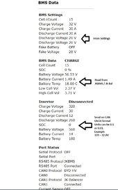
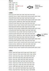
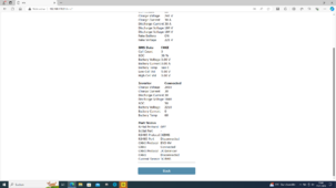
WIFI Web Portal with Cell Info Data on local IP
View attachment 156673
View attachment 156676
Input BMS supported:
View attachment 156674
JK BMS - TTL, BT , CAN
JBD BMS - BT connection
Daly - work in progress
Protocol Emulated:
View attachment 156675
General BMS LV
Document V1.4 - 07.09.2020
CAN: 500Kbps
Transmission Cycle: 1s
Data Mode: Little Endian
Pylonthech LV
Document V1.2 - 08.04.2018
CAN: 500Kbps
Transmission Cycle: 1s
Data Mode: Little Endian
Seplos LV
Document V1.0 - 08.04.2018
CAN: 500Kbps
Transmission Cycle: 1s
Data Mode: Little Endian
LG Resu LV
Document
CAN: 500Kbps
Transmission Cycle: 1s
Data Mode: Little Endian
Growatt LV
Document V1.04 22,02,2019
CAN: 500Kbps
Transmission Cycle: 1s
Data Mode: Big Endian
SMA LV
Document V1.0 - 07.09.2020
CAN: 500Kbps
Transmission Cycle: 1s
Data Mode: Little Endian
Li LV
Document V1.0 06.01.2020
CAN: 500Kbps
Transmission Cycle: 1s
Data Mode: Little Endian
Victron Nemea200
Document V1.0 06.01.2020
CAN: 250Kbps
Transmission Cycle: 1s
Data Mode: Little Endian
Pylon HV
Document V1.18 30.05.2019
CAN: 500Kbps
Transmission Cycle: 1s
Data Mode: Little Endian
GoodWee HV
Document V1.3 31.03.2021
CAN: 250Kbps
Transmission Cycle: 1s
Data Mode: Little Endian
BYD HV
Document
CAN: 500Kbps
Transmission Cycle: 1s
Data Mode: Little Endian
Pylontec RS485
Document V2.0 15.10.2019
RS485: 9600bps MODUBUS ASCII
Transmission Cycle: 0.5s Timeout
Data Mode: Little Endian
Seplos RS485
Document V3.3 21.08.2018
RS485: 9600bps MODUBUS ASCII
Transmission Cycle: 0.5s Timeout
Inverter Replay:
Data Mode: Little Endian
Growatt RS485
Document V2.02 24.07.2019
RS485: 9600bps MODUBUS ASCII
Transmission Cycle: 0.5s Timeout
Data Mode: Little Endian
BYD RS485
Document
RS485: 9600bps MODUBUS RTU
Transmission Cycle: 1s Timeout
Data Mode: Little Endian
Inverter Tested LV
Victron: Gx Family - General LV have the most information displayed, this is an combination of more registry i find.
Growatt SPF 5000 ES - Pylon LV, Seplos LV, Li LV
Growatt SPH 5000 TL - Pylon Lv, Seplos LV, Li LV, Growatt LV
Solis S5-EH1P6k - Semplos LV, LI LV
Deye SUN12K-SG04 - Pylon LV, LI LV
Inverter Tested HV
Fronius Primo 6.0 Gen24 - BYD HV
SunGrow SH10RT - BYD HV
GoodWE GW10K - GoodWee HV, Pylon HV
ThinkPower S100TL - Pylon HV
MultiPack:
If u have 2 packs with 2 JkBms u can combine data by connected 1 to Serial Port and one on BT Port
If u have more then 2 u need to use more interfaces. The Rs485 will be use to communicate between interfaces and Master CAN port will rapport to bms.
Know Issue:
1 - When u use BT connection u can not connect with the phone app to the JkBMS.
U need to stop the interface power and after connect and make settings with ur phone app.
2 - Pylontech LV - if u use this protocol some inverter limit max charge voltage under 54V for 15S LFP battery.
Use Seplos LV or LI LV protocol is same as pylon with few data changed.
3 - From RS485 Protocols i tested only Fronius Gen24, The Pylon RS485 LV and Semplos RS485 LV are write from documentation for PC App -> Battery communication protocol.
Warranties:
The project is under develop NO WARRANTIES are provided ! USE on ur own RISK!
Software:
In this moment GitHub Repo under construction!
Download & Install:
U can download the bin file from my Google Drive Link and write it on ESP32.
For first install u need to be done with cable an pc, after that u can update the firmware OTA.
i will provide new update as soon i can!
drive.google.com
Support my Work:
If u like this project and want to support my work to add more protocols u can invest ur time and also if u can spare some $ will be great too!
Invest Time:
Test the interface on ur inverter and confirm what protocols are compatible to increase invertor compatibility list.
Provide documentation or data communication logs from ur Inverter and OEM battery for reverse engineering new protocols.
Share data if u all ready make some progress on reverse engineering new protocols.
Invest $:
Donate by PayPal and U will receive tech support for ur project :
paypal.me/diyenergy
Fallow on Patreon for last updates.
Buy components kit from my ebay for ur projects.
Documentation:
I share my protocols documentation folder if u want to make ur own software.
if u have any other document of interest share it also with me.
drive.google.com
Other Projects :
WifiManager
https://github.com/tzapu/WiFiManager
TeslaBMS
https://github.com/collin80/TeslaBMS
JKEnuPylon
https://github.com/botaneta/JKbms_Emu_Pylon
JKBmsToPylonCAN
https://github.com/ArminJo/JK-BMSToPylontechCAN
VictronLibCan
https://github.com/jmibk/BMS-LIB-CAN-Victron
Implementation of this interface on battery:
LV 14S 180A Li from Kona with JKBms 150A and Can interface
View attachment 160382
HV 23S / module 60A from Kona with JK Activ Balancer and Can interface
View attachment 160383
JK - Victron
View attachment 160384
JK - Growatt
View attachment 160385
JK - Sungrow
ONLY 10 Pics for post SORRY!
IF U WANT TECH SUPPORT JUST WRITE TO ME, OR WHATUP!


