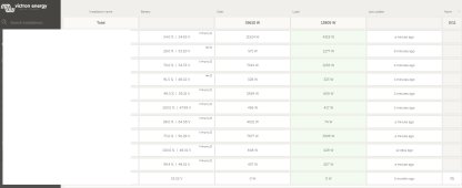
diy solar

diy solar

CAN and RS485 BMS Interface with multiple emulated Inverter protocols for JkBms Jbd BMS Daly 123Smart

This is the simple way to build it DIY , only with CAN port because most of invertors support CAN protocols!

BOM:
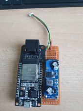
Proto PCB 5x7cm
Esp32 DevKit 1
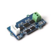
CAN : SN65HVD230
DC-DC: XL7015
RJ45 Breakout with leds
2 x 220R or 330R resistors
1 4 Pin JST 1mm pitch cable


In my Google Drive find Stl file for 3d Printing

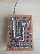
The SN65HVD230 is under the ESP board!

20230801_182451.jpg

Few Soldering
20230801_182457.jpg

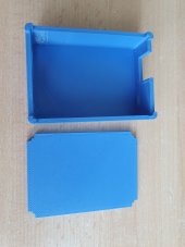
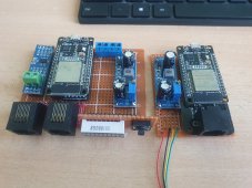
3d Printed Case
20230801_182522.jpg

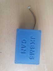
Final assembly
20230606_114051.jpg


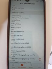
JK - Sungrow HV

20230706_121951.jpg20230706_121956.jpg
 
Yes Chip ID, this is ur key, just put it and confirm it is work!

f43fbd689705fa8d81719a8cf43e4e44

also can u tell me what is ur invertor and the hardware configuration?
Thx the key works.
all fine with the connection.
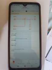
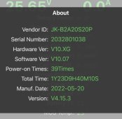
IMG_4146.jpegIMG_4147.png
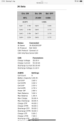
have three wishes:
- display also the cell resistance at the web ui, possible to get over BT.
- let’s change this parameters
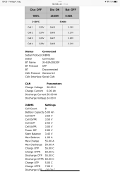
CANParameters
Charge Voltage28.00 V
Charge Current55.00 Ah
Discharge Current50.00 Ah
Discharge Voltage21.60 V
- lest send all infos over MQTT

itˋs a lot but the it´s perfect ???

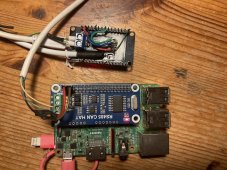
this are my fast build
IMG_4149.jpegIMG_4148.jpeg
 
Last edited:
Thx the key works.
all fine with the connection.
View attachment 160566View attachment 160573
have three wishes:
- display also the cell resistance at the web ui, possible to get over BT.
- let’s change this parameters
CANParameters
Charge Voltage28.00 V
Charge Current55.00 Ah
Discharge Current50.00 Ah
Discharge Voltage21.60 V
- lest send all infos over MQTT

itˋs a lot but the it´s perfect ???

this are my fast build
View attachment 160574View attachment 160575
The value ar not a fix value to be inserted manual. They are calculated by ur jkbms settings.

Charge Voltage is calculated OVPR * No Cells
Charge Current is Charge Current from settings
Discharge Volatge is UVPR * No Cells
Discharge Current is Discarge Current from settings

Limits activated per cel value:

Charge Current is limited from OVPR -> OVP 100%-0%
Discharge Current is limited from UVPR -> UVP 100%-0%

Same on temps


What is ur inverter?
Can verify the data received by inverter from the CAN?
 
Last edited:
Nice to know your work.
In my case I have a Goodwe EM5048 with DIY battery and DALY BMS.

So far there is no communication between them.


The bad part of this is that when Goodwe thinks the battery reaches 100%, it stops charging, even though it really is at a different SOC in DALY.

Do you think it would be feasible to emulate a fictional SOC of 60%? so that it does not limit upload or download?
Thanks
Can u give me the daily model of bms? i can take the data from daly if u need to send it to Goodwee
 
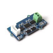
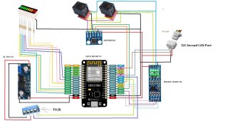
For Hv Systems series i use Jk Active Balancer with can port, and for that i need 2 can ports one for jk on 250kbps and other for inverter with 500kbps, in this version i use a second can port on i2c

mcp2551-mcp2515-seri-can-bus-modulu-en-arduino-modules-seeedstudio-32440-11-B.jpg

U can try also on SPI, but the MCP2515 will not work with 3.3V, but u can use MCP2517

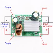
Also if u want to use it with HV u need to change the XL705 step down with :

DC-9V-12V-24V-36V-48V-72V-84V-120V-to-5V-3A-Step-Down-Module-Power.jpg

If someone make this setup for HV invertor, contact me for more details.
 
The value ar not a fix value to be inserted manual. They are calculated by ur jkbms settings.

Charge Voltage is calculated OVPR * No Cells
Charge Current is Charge Current from settings
Discharge Volatge is UVPR * No Cells
Discharge Current is Discarge Current from settings

Limits activated per cel value:

Charge Current is limited from OVPR -> OVP 100%-0%
Discharge Current is limited from UVPR -> UVP 100%-0%

Same on temps


What is ur inverter?
Can verify the data received by inverter from the CAN?
Hi,

thx for answer.
But this parameters are not fine for me.
At my 24V Akku I use as
discharge voltage 3V x 8 = 24V as limit.
for the charge and discharge current there is an display issue the masure are A and not Ah ?

I use Victron MultiPlus within this will managed by Venus OS run at the RPI.
Yes I see all Parameter at the Venus OS via CAN.

last but not least I´ll donate some money ? for you can I get your PayPal name pls.
regards

I look in ur settings and something is not right.
Power Off value of the cell is bigger then UVP and UVPR
If u load the default settings for LI, LFP in jk will se the power off if the smallest.

Jk will work like that :

Power off is used to shutdown the bms because if remain in standby in time will discharge more from battery.

UVP - will close the discharge mosfets if one cell reach UVP - u use the smart interface to tell victron to stop discharge before that
UVPR - after an UVP event JK will open the discharge mosfets after all cels are more then UVPR

Power OFF < UVP < UVPR - in ur case settings are not right.

Because the interface will reduce current before UVP happens the UVP event will not ampere.
in ur case if u want to discharge to 3V need this settings

UVPR 3V
UVP 2.9V
Power Off 2.8V

For charging if is LFP

OVPR 3.45 if u want 80 DOD
OVP 3.5

with this settings will work ok.

Also is important to know Victron use only CVL , CCL, DCL, if u go to parameters on the victron console will see DVL is not show there.
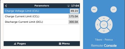
victron.jpg


The discharge limit is set by the current!
And also u need on Multiplus Veconfigure the dc low shutdown to be at uvp*nr cells , not at jk poweroff * nr cells
 
  • Like
Reactions: juf
Hi,
I try today the serial connection.
wonˋt work ??‍♂️
Bluetooth all fine.
yes I have change the cable tx/rx and return.
 
Hi,
I try today the serial connection.
wonˋt work ??‍♂️
Bluetooth all fine.
yes I have change the cable tx/rx and return.
Do u change the protocol on Serial Connection?
U connected on GPS TTL Connector?
I upload a new bin with Serial an Bt Connection u can activate one or other. Or both if u have tow jk one on Serial other on BT

serial.jpg

JKBMS GPS <-> ESP32 Dev Kit 1

from left to right

GND - GND
RXD - Gpio 17 TXD2
TXD - Gpio 16 RXD2
VCC - to step down IN+ (at least 80Vstep down)
 
Last edited:
Do u change the protocol on Serial Connection?
U connected on GPS TTL Connector?
I upload a new bin with Serial an Bt Connection u can activate one or other. Or both if u have tow jk one on Serial other on BT

View attachment 160903

JKBMS GPS <-> ESP32 Dev Kit 1

from left to right

GND - GND
RXD - Gpio 17 TXD2
TXD - Gpio 16 RXD2
VCC - to step down IN+ (at least 80Vstep down)
sure I have change the protokol.
at your pic IMG_4150.jpeg you have other pin for.
I‘ll try with the new gpio.
regards ??
 
sure I have change the protokol.
at your pic View attachment 160955 you have other pin for.
I‘ll try with the new gpio.
regards ??
IMG-20230409-WA00041.jpg

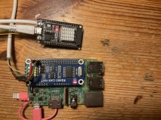
Ports :
Blue One to JK BMS GPS port with the DC step down for power in

The white JST one is I2C bus to can use a second CAN port for HV system to communicate with JK Active Balancer.

mcp2551-mcp2515-seri-can-bus-modulu-en-arduino-modules-seeedstudio-32440-11-B.jpg

I forgot to mention, i have more then one hardware design u need to change the Interface name.
20230804_080831 (1).jpg


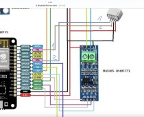
For BT CAN and Serial CAN - there are not RS485 support here - for u use that !

rx tx pin are 16 17 - the standard Serial 2 of esp32

If u want add LEDS on this PINS:

Connect 32
Send 33

For RS485 CAN interface

16 17 is used for RS485
18 19 is used for Serial connection with jk BMS

On dual Can

i2c port is used for the second CAN port.
 
Last edited:
  • Like
Reactions: juf
View attachment 160957

Ports :
Blue One to JK BMS GPS port with the DC step down for power in

The white JST one is I2C bus to can use a second CAN port for HV system to communicate with JK Active Balancer.

View attachment 160969

I forgot to mention, i have more then one hardware design u need to change the Interface name.
View attachment 160971


For BT CAN and Serial CAN - there are not RS485 support here - for u use that !

rx tx pin are 16 17 - the standard Serial 2 of esp32

If u want add LEDS on this PINS:

Connect 32
Send 33

For RS485 CAN interface

16 17 is used for RS485
18 19 is used for Serial connection with jk BMS

On dual Can

i2c port is used for the second CAN port.
Thx so I try out 16 and 17 or 18 and 19.
but at the google drive I don’t find any new bin file.
as i flash thisIMG_4151.png
??‍♂️
 
Thx so I try out 16 and 17 or 18 and 19.
but at the google drive I don’t find any new bin file.
as i flash thisView attachment 160975
??‍♂️
if u use esp32 devkit 1 with CAN BT interface name selected in Setup

the serial connection is the standard Serial 2 port
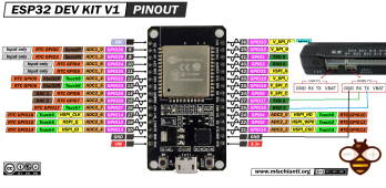
RXD2 GPIO16
TXD2 GPIO17

if u use other esp32 board need to see where TXD2 and RXD are maped.

Fallow this connection!

ESP32-DOIT-DEV-KIT-v1-pinout-mischianti.png

AFTER SAVE SETTINGS AND CHAGED THE PROTOCOL TO SERIAL AND NAME OF THE INTERFACE RESTART THE INTERFACE!!!!
 
  • Like
Reactions: juf
Where I can find „I upload a new bin with Serial an Bt Connection u can activate one or other. “?
 
Where I can find „I upload a new bin with Serial an Bt Connection u can activate one or other. “?
Gdrive

If u have only one JK select BT protocol OFF
If u have 2 JK select one on serial and other on BT
 
Last edited:
  • Like
Reactions: juf
Hi, runs fine with serial now.
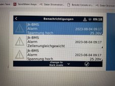
but the alarms are wrong

image.jpg

i charge to 28V
with this parameters
IMG_4152.png
 
Last edited:
Hi, runs fine with serial now.
but the alarms are wrong

View attachment 160979

i charge to 28V
with this parameters
View attachment 160983
OVPR 3.5V * 8 = 28V

Alarm max cell v - min cell V > 0.2V -> Cell inbalance Error trigger

Alarms if cell V > OVP
Worning if cell V >OVPR + (OVP-OVPR)/2

When u boot the interface first time, until settings data are received by serial some vars are saved default for liIon
float UVP = 2.9;
float UVPR = 3.2;
float OVP = 4.2;
float OVPR = 4.1;
float MCC = 50;
float MDC = 100;
float COTP = 70;
float COTPR= 60;
float DOTP = 70;
float DOTPR= 60;
float CUTP =-20;
float CUTPR=-10;
float MOTP = 90;
float MOTPR= 70;
int CC = 16;
float NBC = 100;

tell me if the error apers onli on boot or after?

U need to put start balance from 3.2 V on lfp. Jk is an active balancer not a resistiv one to start balance in top.

victron1.jpg

I use this interface on many my victron systems and work ok .
Seems to me u have some settings issue.
Can u share ur vrm plant with my account to see the problem mrconstantin84@gmail.com
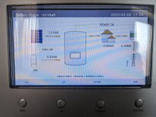
When wornings or error apers check on console on bms -> details will see the voltage of min max cells and other data received by victron from bms
 
Last edited:
  • Like
Reactions: juf
I think you right, this issue are only after boot. ?
this system are not online is my Testsystem
 
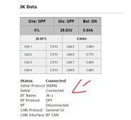
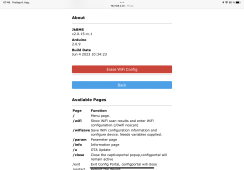
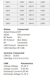
I add on Info page the last MSG received from invertor for easy debug the connection

If u dont receive any CAN MSG that mean is a hardware problem in ur setup.
If u receive msg there and invertor tell CAN comm error that mee the protocol is not ok.

canmsg inverter.jpg

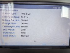
Solis Inverter Comm

PXL_20230502_112806743.jpgPXL_20230505_110544894.jpg
 
Hello! Can the RS485 signal be sent to for example Solar Assistant as well or is just only for comms between BMS-s? If yes, would the wiring be the same as on the first page and on the Google Drive pictures?
 
Back
Top