diy solar

diy solar

Can not wrap my head around which BMS to use.

Berk8520

New Member
Joined
Dec 3, 2019
Messages
19
_AejXrDzogCrfqIDLnd0wCHLdhAa3GWk6Gm06nGJ86srpZDVwVFnNv2UnyUGYNghfeoAOxqBXpo8gigVIGRDDeLeBe_wH3ON3wx_t-p83ZyH5NlucNCSiFqbQNn7WhQnWsAMQa8YGHupED1uwfhuAtrpHYNvt2g9Dm3vjJE7zECP9fZtQhCC0X6rYYr6gFJ64vwVgwuB2m6m5rUzL7nphXKtRovUrqmtyFizHTSASEbxOFPg3OOXDRdUcWniRfUtL0n73E29XGTph9o6YISN0wBnl-NkCQMCGi0OkrxF_K_t4H0IX6fEofABTmdBkI7vTArHkDuuhEUe-niLB476r6qSc01hSNqe85rpUea31fTjyVOf0ps0VLQgp1_3klPFvGG49CVqoJ3jhWGSs2_hcINBk2V7JXh9lc6uRDgr1HC29mI-u60FGut-r4Mu3-kWV_or7_oY3hgr4Wq-Tt3OL2tW_HRWIDjw0MtIDD_YhxNzmTnpRyTo0uaqfBtRi4tJrRvr2Od19K3tiqXCwFY6SW7Nbmt0xlDr5sslD0g3voFokSVIU8NpVHKjOXxvZW-3oQFXLXA5-046K1dhbJVtnR0eMlRvGPM8RP6boLPCvBmbNufXV-Ff1_b-UF70fWjWC1SkV7kBKQj4_rbcfGEvZyYwqJ3cTz2WMsxWt3WNIVE6JVkgoig6VLyLWiAYIqw=w910-h615-no


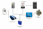
Above is my current system in my van. The only difference is currently I have 350 AH of AGM. I have a 4S 280 AH battery on the way. The questions I am wrestling with are:

1. Which BMS would work best? Maybe one of these Daly bms's at 250 amps?
2. Will recommends connecting the SCC directly to the batteries. My SCC does have Low temp cutoff by but what about the charge from the van how do I handle that? Can I run the 30 amp charger through the BMS?
3. My largest draw is from a water heater and an induction cooktop both 1400 W at 120 V. That means on the 12 V side I am pulling +-120AMP so from what I have read it is recommended that the BMSbe de-rated by 50% and I should be looking a 250 amp BMS?

Thank for helping a lithium newbie out :)

Berkeley
 
Depends on perspective. Van is my and my SO's full time home and place of work. so in the sense very minimal :)

The system diagram you attached only shows a cat's eyeball rotated 90 degrees.
 
_AejXrDzogCrfqIDLnd0wCHLdhAa3GWk6Gm06nGJ86srpZDVwVFnNv2UnyUGYNghfeoAOxqBXpo8gigVIGRDDeLeBe_wH3ON3wx_t-p83ZyH5NlucNCSiFqbQNn7WhQnWsAMQa8YGHupED1uwfhuAtrpHYNvt2g9Dm3vjJE7zECP9fZtQhCC0X6rYYr6gFJ64vwVgwuB2m6m5rUzL7nphXKtRovUrqmtyFizHTSASEbxOFPg3OOXDRdUcWniRfUtL0n73E29XGTph9o6YISN0wBnl-NkCQMCGi0OkrxF_K_t4H0IX6fEofABTmdBkI7vTArHkDuuhEUe-niLB476r6qSc01hSNqe85rpUea31fTjyVOf0ps0VLQgp1_3klPFvGG49CVqoJ3jhWGSs2_hcINBk2V7JXh9lc6uRDgr1HC29mI-u60FGut-r4Mu3-kWV_or7_oY3hgr4Wq-Tt3OL2tW_HRWIDjw0MtIDD_YhxNzmTnpRyTo0uaqfBtRi4tJrRvr2Od19K3tiqXCwFY6SW7Nbmt0xlDr5sslD0g3voFokSVIU8NpVHKjOXxvZW-3oQFXLXA5-046K1dhbJVtnR0eMlRvGPM8RP6boLPCvBmbNufXV-Ff1_b-UF70fWjWC1SkV7kBKQj4_rbcfGEvZyYwqJ3cTz2WMsxWt3WNIVE6JVkgoig6VLyLWiAYIqw=w910-h615-no


Above is my current system in my van. The only difference is currently I have 350 AH of AGM. I have a 4S 280 AH battery on the way. The questions I am wrestling with are:

1. Which BMS would work best? Maybe one of these Daly bms's at 250 amps?
2. Will recommends connecting the SCC directly to the batteries. My SCC does have Low temp cutoff by but what about the charge from the van how do I handle that? Can I run the 30 amp charger through the BMS?
3. My largest draw is from a water heater and an induction cooktop both 1400 W at 120 V. That means on the 12 V side I am pulling +-120AMP so from what I have read it is recommended that the BMSbe de-rated by 50% and I should be looking a 250 amp BMS?

Thank for helping a lithium newbie out :)

Berkeley

1. That BMS is pretty new and I don't think there is much experience on the forums on it yet.
2. Yes the Orion charger should go through the bms.
3. 1440 watts / .85 efficiency factor / 12 volts = 141.176470588 dc amps. I think 250 "Daly" amps is realistic for ~140 amps.

You don't have a discrete Low Voltage Disconnect.
Are you going to rely on the BMS for LVD?


Is there a BMS that is better understood by the community that would fit the bill? I was thinking that was one of the main reasons for a BMS? Balancing and low/high voltage disconnect? Is there a better way? The inverter also has low voltage disconnect. We don't run the inverter full time just turn it on while we use it and then flip it off when done.
 
Last edited:
IS there a BMS that is better understood by the community that would fit the bill? I was thinking that was one of the main reasons for a BMS? Balancing and low/high voltage disconnect? Is there a better way? The inverter also has low voltage disconnect. We don't run the inverter full time just turn it on while we use it and then flip it off when done.

The normal Daly should fit the bill unless you need low temp cutoff.
Check its LVD value but I think it will be too low.
Unless its an iverter/charger the low voltage disconnect is likely too low and not configurable.
What is the LVD value for the inverter?
The DC loads should also have LVD protection.
If you only have to protect the dc loads then the Victron battery protect is probably a good choice.
If you have to protect everything then this one should be good https://www.sterling-power-usa.com/ProLatch-R-240amp12vor24v.aspx
 
You might not want to put the LVD in line with the charge sources.
If it trips you won't be able to charge.
 
I also notice you don't have a shunt or hall sensor.
I highly recommend one.
 
I agree with Joey here. Ideally low voltage disconnect should only cut the loads, and leave chargers to do their thing. This requires a BMS capable of controlling charge and discharge current separately (most are--but some like Daly have restrictive current limits on the charge side).

Personally, I would not follow Will's example in some older videos where he recommends having your SCC bypass the BMS. I don't think he is wrong necessarily, but I have a different risk tolerance, and I think its an unnecessary risk that can be avoided with a properly designed system. I think a BMS should be able to cut all charging and all discharging in most design scenarios. I think his example was based somewhat on cost, expedience, and parts on hand, and in further videos he demonstrated better methods.

But as I mentioned earlier, this is just my personal opinion, based on the little sliver of understanding I have, and my preferences and goals. Take it with a grain of salt.
 
I guess one thing I am struggling with is spending $1000 to protect $500 worth of batteries. In a perfect world a BMS in my understanding would protect for over voltage, low voltage on both charge and discharge and then of course there is the low temp disconnect. Is there a BMS that has all three that can handle the amperage I am using? Dzl you mention a "Properly designed system" and that is what I am trying to get to but the more I read on this forum and others the more conflicting info I find. Another solution I was looking at was the Electrodacus but it seems I would be in that several hundred dollars very quickly.
 
Last edited:
I guess one thing I am straggling with is spending $1000 to protect $500 worth of batteries.

You easily could spend that much, but you definitely don't need to spend anywhere near that amount adequately protect your batteries. Though low cost options are limited for high current systems.

In a perfect world a BMS in my mind would protect for over voltage, low voltage on both charge and discharge and then of course there is the low temp disconnect.

I would say LVD and HVD are baseline requirements for a BMS, low temp protection is ideal but extra, and in many cases not required. The cheapest/often easiest solution is to make sure your batteries aren't in sub zero conditions, if they are or might be, low temp protection of some sort should be used.

"Properly designed system" and that is what I am trying to get to but the more I read on this forum and others the more conflicting

I feel your pain, there is a lot to wrap your head around, and the landscape is constantly evolving. There is a lot of good info out there but its scattered and evolving as the market changes and as our shared knowledge evolves.

Another solution I was looking at was the Electrodacus but it seems I would be in that several hundred dollars very quickly.

This is my current top choice for my application, but it doesn't work for everyone. It can do all the things you want and then some, but its a pretty non-traditional BMS, it doesn't directly control anything, it is designed to work with components that can be controlled remotely. This is in my opinion a very elegant solution, but it requires choosing components that are capable of remote control, if you have already purchased your components you would need to check whether your devices can be controlled in this way, or use workarounds to accomplish this.

The BMS itself is under $150 USD iirc, you will need to purchase a shunt or two but that is a good idea with any system. The price could be quite a bit higher though if you need to replace components you've already bought or buy extras.

You also have to understand you are buying a more advanced, less beginner friendly, DIY BMS with a steeper learning curve and smaller community
 
Last edited:
In a perfect world a BMS in my mind would protect for over voltage, low voltage on both charge and discharge and then of course there is the low temp disconnect. Is there a BMS that has all three that can handle the amperage I am using?

I'm not clear on how much amperage you are designing for. Lets start there, lets try to outline your requirements, and maybe that'll help clarify which BMS would work best for you.
  1. Max charging current = 80A
  2. Max discharging current = ???
  3. How likely are sustained temps near freezing (in your battery compartment)?

(remember that the 0*C / 32*F minimum temperature for LFP refers to the (1) internal cell temperature, and (2) the minimum temperature for charging--your batteries have a lot of thermal mass so temperature will be slow to change. Point being, if temps dip down to 0*C a few times a year for a few hours in the middle of the night, you don't have much to worry about if your batteries are in an insulated space. But if true sub zero temps are common--especially in the day when your PV array is productive--low temp protection is a bigger concern)
 
Last edited:
So I do have all the components with the exception of the DC to DC charger. I don't believe my SCC has a remote switch ability. My Aims nveter does have a remote switch that is currently wall mounted. My largest amp draw is the water heater at 140 amps. The solar charge controller is a 50 amp controller. The DC to DC charger would be a 30 amp charger. The batteries will live in the cab of my van. There is a furnace and we mostly travel in temperate climates but do go skiing several times a year.
 
So I do have all the components with the exception of the DC to DC charger. I don't believe my SCC has a remote switch ability. My Aims nveter does have a remote switch that is currently wall mounted.

If you went the SBMS route you could use a 65A Victron Battery Protect in reverse to control the charge controller. You would need another battery protect for your DC loads, and you would need to determine if your inverter's remote on/off is compatible with the SBMS (I believe most but not all are with a little modification). The DC-DC charger in your picture is compatible.

My largest amp draw is the water heater at 140 amps.

This is a good start, but you need to calculate or estimate the total AC + DC loads that might be running at a given time. Your discharge current is almost certainly going to be what dictates the size of your BMS, so the task at hand is figuring out what the max discharge current could be.

From the sound of it, the 250A Daly you mentioned would cut it, it is rated for 125A charge rate, so that should safely accommodate your 80A max charge rate. We won't know whether the 250A limit is sufficient until you can better account for your loads.
 
Loads are fairly minimal. We have a Dometice fridge that runs all the time. I think it draws 5 amps 12 V when the compressor is running. We have all LED lights. We charge phones and laptops. We also have an electric kettle 800 watts at 120 and an induction cook top 1100 watts. We only turn on the hot water heater before we want to shower. We only turn on the inverter during actual use and we never run more than a single high draw 120 appliance.
 
Loads are fairly minimal. We have a Dometice fridge that runs all the time. I think it draws 5 amps 12 V when the compressor is running. We have all LED lights. We charge phones and laptops. We also have an electric kettle 800 watts at 120 and an induction cook top 1100 watts. We only turn on the hot water heater before we want to shower. We only turn on the inverter during actual use and we never run more than a single high draw 120 appliance.

Okay that helps put things in perspective. So as long as you can make sure to never use any of your big 3 electrical consumers at the same time, or at least not run more than two simultaneously on occasion

Kettle: 800 / .85 / 12 = ~80A
Stove: 1100 / .85 / 12 = ~105A
Water heater 1440 / .85 / 12 = ~140A

Based on the DC loads you have outlined, I think it would be safe to say DC loads would not exceed 50A total. Most likely not even half that, but that depends on the specifics.
 

diy solar

diy solar
Back
Top