Hello!
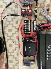
Fairly new to this stuff. I am hooking up a Renogy setup to my truck camper. my gear is the following:
-100W Renogy flex panel
-50A Renogy DCDC MPPT charge controller
-100AH LiFePo Battery
- 8 Gage solar panel extension cables (https://www.amazon.com/dp/B09GV5TVY1?ref=ppx_yo2ov_dt_b_product_details&th=1)
- 4 gage wire running to Battery
Problem: When hooking my panel to my extension cables that take my panel up to the top of my camper, my charge controller does not read a signal. It does however read signal +/- 75W charge to my battery when hooking the panel directly to my charge controller (Skipping my extension lines and thus not allowing me to mount my panel on top of my camper).
I have tested everything I could think of with exception of just swapping out my extension cables.
-I have continuity on both my red and black extension cables meaning connections appear sound
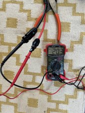
-Multimeter reads POSITIVE 20V when reading AT THE END of my extension cables when panel is hooked to them, so my polarity seems to be correct and continuity is verified
-Tried on my Renogy Rover charge controller, same outcome
-Tried with different solar panel, same outcome
My extension cables are 8 Gage prebuilt cables purchased off amazon and the entire remaining cable setup uses 4 Gage. I assume it is my cables that are to blame? Voltage drop? voodoo magic curse??
What is wrong here?? I have tried everything I can think to do. Is there something I am missing here? Do I need higher quality extension cables?
I appreciate any advice you can provide. Feeling pretty dumb right now.


