diy solar

diy solar

Charge controller

Ok here's another stupid question for you experts in this field.lol
I'm learning a lot but much more needed.lol
Victron charge controller needs to be grounded ? Do I put the wire to the trailer frame , to the negative of the battery ??
I'm not getting this bus bar thing and we're t ground ..
Pretend I'm a child and someone draw mea picture .lmao
 
I ran my Victron grounds to the frame of the trailer.

I did use 6 awg cable from the solar charge controller to the common bus bar. My cable is maybe 2' on each leg (pos/neg) but I wanted to minimize voltage drop and I standardized on 6 awg for just about everything else except the batteries and the inverter.
Ok so I can ground to trailer .. I was reading that was the way but ok perfect ..
Now if you don't mind , explain this bus bar thing ?? Do i need one for my simple set up ??
 
Wasn't the way to ground but if you did it and it works , perfect and simple.
 
I bought a ground bus bar from Home Depot. It was less than $10 a couple years ago. I ran all the equipment grounds to the ground bus bar, then a single cable from the ground bus bar to the trailer's frame.

Terminal Ground Bar Kit

That's for the equipment grounds only.

The positive and negative cables are all connected at a set of common bus bars. These can vary from four post bus bars with 3/8" studs to eight post bus bars with 5/16" studs and a smattering of smaller screws on the bar for smaller wires. Is it necessary? It depends. The more you have to connect the easier it is if you use a common bus bar. The terminals on some devices can support two, maybe three, lugs attached on the stud. Some can support more but there is a limit to how many you should stack.
I'm a visual guy so is this correct way??
Without inverter and with ..
 

Attachments

  • 20220712_171900.jpg
    20220712_171900.jpg
    73.8 KB · Views: 4
  • 20220712_171715.jpg
    20220712_171715.jpg
    70 KB · Views: 4
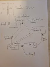
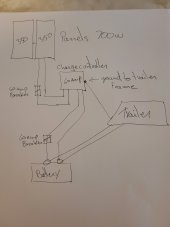
Yeah, that works. The line from the inverter to shore power is to tie into the trailer's 120v AC side? If so, it may not be quite right.

Your breakers aren't quite right.
The breaker from the PV to the solar charge controller would need to be about 25 amps if the panels are wired in parallel. 15 amps if in series. This breaker is more of a switch than over current protection but it still needs to be sized right.
The breaker from the solar charge controller to the battery needs to be larger than 60 amps. Rated amps x 1.25 is what we recommend to avoid nuisance trips. Call it 75 amps.
Breakers that handle the number of amps an inverter can draw are expensive. Most installs use a fuse in that position. We like to see a Class T fuse immediately downstream of the battery on the positive leg.

Check out this diagram published by Victron Energy. It's overkill but it does a very good job of showing how a set of common bus bars, switches, fuses, batteries and devices get wired up.


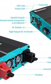
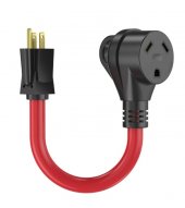
Many inverters have an AC input port. The shore power cables (pos, neg, ground) will come into this port. The output of the inverter would then go to the main distribution panel of your trailer. Currently, the shore power cable goes into the main distribution panel. You'll disconnect the shore power cable from the main distribution panel and run it to the inverter instead. A new/longer cable may be necessary. My shore power cable came into an Automatic Transfer Switch (to switch between generator and shore power), so I replaced the cable that went from the ATS to the main distribution panel. The new cable goes from the ATS to the inverter. Another new cable of the same gauge goes from the inverter to main distribution panel.

If you don't have an on-board generator then you won't have an ATS. The inverter will have an internal ATS that keeps you from inverting 120v AC while the shore power circuit is also active (plugged into a pedestal).

The above leads into a discussion about the converter. An inverter like the Victron Multiplus is an inverter/charger and replaces the converter that your trailer came with. The OEM converter is probably not LiFePO4-friendly. Also, leaving it in place when implementing an inverter can lead to a loop. Battery -> Inverter -> Converter -> Battery
 
Wow info overload .lol
I'm an idiot for this stuff remember but that's awesome knowledge to absorb..
Ok on the breaker size , will switch and as for fuse going from battery to inverter I'll have to wait to see the size of inverter I get correct??
Ya I was told to turn the breaker off for my converter...
Now can I or can't I just plug my shore power on trailer directly into inverter???
 
By the way I want to thank you so much , you've been and continue to be extremely helpful and I appreciate it very much..
We're you from ?
 
Ya I was told to turn the breaker off for my converter...
Now can I or can't I just plug my shore power on trailer directly into inverter???

Yes, you can just turn off the breaker for the converter. The converter will still be connected to the 12 volt side and it draws a very small amount of amps, but not enough to drain your new battery over 120 days.

Can you clarify what you mean about plugging the shore power into the inverter? I think you want the inverter to be standalone, meaning that your trailer won't have any AC power unless you plug the shore power cord into the inverter (or a pedestal). If that's the case, that is an option and would eliminate the need for an ATS. However, you may need to wire up a 30 amp outlet off of the inverter. My inverter is intended to be hard wired - there are no outlets on it.
 
So not sure what inverter I'm getting yet, but something like this ..
Battery cables in one side and plug to trailer shore power to the other..
Would that work ?
Don't want to hard wire if I don't have to if this works.??
Just though this way was easier if it works ..???
 

Attachments

  • Screenshot_20220712-220743_Amazon Shopping.jpg
    Screenshot_20220712-220743_Amazon Shopping.jpg
    123.2 KB · Views: 3
  • Screenshot_20220712-220857_Samsung Internet.jpg
    Screenshot_20220712-220857_Samsung Internet.jpg
    41.6 KB · Views: 3
Ya I've decided to do it right an go wit the victron , great reviews ..
The 60 amp charger from what I can see holds 6 awg wire max.
Do I need Tha big a wire , they say yes ..lol
When stating 6 AWG they are looking at the controller maximum specifications and not what amps the panels will be producing. 10 AWG is fine From your panels to controller. Run 6 AWG from your controller to your batteries..

Sry in Dubai at the moment on my way to sunny Mykonos.
 
Last edited:
So not sure what inverter I'm getting yet, but something like this ..
Battery cables in one side and plug to trailer shore power to the other..
Would that work ?
Don't want to hard wire if I don't have to if this works.??
Just though this way was easier if it works ..???

It's a workable solution. There is another forum member that went with that as his initial solution.

The outlets on that inverter may be rated for only 10 or 15 amps. Your shore power connection can handle up to 30 amps. If you keep the AC-side loads to under what the outlets are rated for you'll be OK. Be sure you look at the AC output specs to know for sure what you're getting.
 
Why are you getting a 60A solar controller unless you are planning on adding more panels later. Your panels total 19.6A total so a 30A controller will do. When stating 6 AWG they are looking at the controller maximum specifications and not what amps the panels will be producing. 10 AWG is fine.

Sry in Dubai at the moment on my way to sunny Mykonos.

Two 350 watt panels have the potential to produce almost 60 amps (700 watts / 12 volts = 58 amps). A 60 amp controller isn't too much controller. Sure, the panels are unlikely to ever produce the full 700 watts. But if he bought a 50 amp solar charge controller he might be leaving some amps on the table.
 
No you are not able to plug shore power directly into your inverter. I’m not sure what that cable is that you have posted is it to connect from a shore power source to a trailer.

In Australia we generally use 10A for domestic services with a dedicated circuit say to a cook top with a 15A circuit. So normally we plug an extension cable in the 10A shore power and have a short cable that have a different plug on it to connect to a trailer Because the pins on 10A and 15A are different.
 
Two 350 watt panels have the potential to produce almost 60 amps (700 watts / 12 volts = 58 amps). A 60 amp controller isn't too much controller. Sure, the panels are unlikely to ever produce the full 700 watts. But if he bought a 50 amp solar charge controller he might be leaving some amps on the table.

Yeah my bad I didnt look at the panels current. I’m sitting at an airport when I should be fast asleep in bed.
 
Last edited:

diy solar

diy solar
Back
Top