diy solar

diy solar

Chargery BMS communications.

You couldn't have posted that a couple of days ago eh ! I would have taken that image and made a variation for the new Chargery BMS manuals I just finished up and sent to Jason @ Chargery. Although they got more drawings & examples too in all of them, so.

Apologies for that.
 
I will play with it that would be somewhat simpler than the websocket for sure.

Hi Craig.

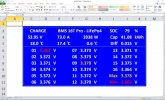
On the Chargery website, they have a small test program "USR-TCP232-Test V1.4.exe", when the unit is set up as "TCP Client", the test program shows the data coming from the BMS as "Network Data Received" as per the attached page. At Least this confirms the data to be converted from the BMS Comm port to my LAN.
 

Attachments

  • USR-TCP232-Test V1.4.pdf
    185.9 KB · Views: 41
This is my problem "Windows 98/2000/XP/Vista/7/8/10" EFF windows lol when is the world going to learn other OS's are much better for this sort of thing.
Thee is source code for this on GitHub too. There are APK's and also for other OS platform like NIX but I'll leave the digging to you, not hard to find. If google fails, try DuckDuckgo.
 
Great read! I needed a Modbus serial solution, to took the following approach:

[Chargery]-[RS232toTTL converter]-[Arduino MEGA]-[RS232toTTL converter ]-[cellular RTU]

The MEGA was a good fit for this since it has several UARTs onboard (no need for the added complexity of SoftwareSerial library). The MEGA parses the byte stream and stores the data in an integer array. The RTU polls the integer array every 5 seconds then texts me if anything is amiss, otherwise it sends a daily report via email.
 
Mario,
Thanks for the screenshots! Impressive job!
Are you open to sharing a little context on how you chose 0 seconds for your cut-off delay time? Is there a scenario where if you set this for a few seconds you'd have some risk of catastrophe?

I realize our systems are different, mine is 12V, 280Ah in an RV. I had thought a bit of delay, say up to 15 seconds may allow for some motor in-rush or other high-draw startup.
Also, what is the max delta V that you've experienced? I have very few cycles and under high load (150A) I saw 35mV or 40mV. So I moved my max to 75mV, but maybe 100mV is better. I don't want the battery to disconnect unnecessarily.

Thank you,

Doug
 
I would definitely set it at 100 or even above. I set mine at 300 to me it is more important to not go above or below certain voltages and if the cells are off balance in the middle. I would like to know that but no need to shut things down because of it.
 
Mario,
Thanks for the screenshots! Impressive job!
Are you open to sharing a little context on how you chose 0 seconds for your cut-off delay time? Is there a scenario where if you set this for a few seconds you'd have some risk of catastrophe?

I realize our systems are different, mine is 12V, 280Ah in an RV. I had thought a bit of delay, say up to 15 seconds may allow for some motor in-rush or other high-draw startup.
Also, what is the max delta V that you've experienced? I have very few cycles and under high load (150A) I saw 35mV or 40mV. So I moved my max to 75mV, but maybe 100mV is better. I don't want the battery to disconnect unnecessarily.

Thank you,

Doug
Hi Doug.

The default for the cutoff time is 10 sec. For my scenario I set it for safety to 0 seconds, I have a 1000Ah 52V lithium iron battery on my solar system for my house and can turn catastrophic if things go wrong. I do have circuit breaker protection also, but rather play it safe.

Generally my delta voltage is around 10 to 20mV if I can fully charge the battery each day. I have found that if I have 2 or 3 consecutive cloudy days where I could not fully charge the battery, that I can see up to about 40 to 50mV delta on the top end when it is fully charged again. So my 100mV is just a bit of a margin so the battery stay connected while the BMS take care of the balancing.
 
Mario and Craig,
Thanks for the feedback. I do have a large AGM battery as backup if the LFP were to trigger a fault, but I don't want false positives. I'll think more about the delay and voltage differential. Mostly, I need to get more cycles on my system with some manual monitoring. But hard to do on lockdown at home!
Cheers,

Doug
 
Nice job Craig! I've been also working on BMS communication. I'm curious, have you done a data stream? I'm using an Arduino to read the stream. Here's what I get from Putty:

24 24 57 F D 98 2 0 0 0 97 0 97 5F E2
24 24 56 16 C F6 C FD C FE C F9 0 0 0 0 0 48 0 1E 5F 93
68 3A 3A 33 D A
24 24 57 F D 98 2 0 0 0 97 0 97 5F E2
24 24 56 16 C F6 C FD C FE C FA 0 0 0 0 0 49 0 1E 5F 95
24 24 57 F D 98 2 0 0 0 97 0 98 5F E3
24 24 57 F D 98 2 0 0 0 97 0 97 5F E2
68 3A 3A 33 D A
24 24 56 16 C F6 C FD C FE C FA 0 0 0 0 0 49 0 1E 5F 95
24 24 57 F D 98 2 0 0 0 97 0 97 5F E2
24 24 56 16 C F6 C FC C FE C FA 0 0 0 0 0 46 0 1E 5F 91
24 24 57 F D 98 2 0 0 0 97 0 98 5F E3
68 3A 3A 33 D A

The 68 3A 3A 33 D A is an odd ball. There's no documentation about this data packet. Have you seen it?
 
I'm using an Arduino to read the stream.
Cal, welcome to the forum! I’m using an Arduino Mega to parse the Chargery data into a Modbus array, and have seen the same undocumented data stream. It may be for when the BMS is connected to a Chargery charger, like this. “Remote control charge current” feature is what got my attention.
 
If the Chargery BMS is used in conjunction with a Chargery power supply ..... it will control the charge current from the power supply .... So, maybe it is related to this.
 
Cal, welcome to the forum! I’m using an Arduino Mega to parse the Chargery data into a Modbus array, and have seen the same undocumented data stream. It may be for when the BMS is connected to a Chargery charger, like this. “Remote control charge current” feature is what got my attention.

Thanks for the welcome! I'm also using Mega to data log. You are probably correct that the unknown packet is connected to the remote charger. I've found the data stream is somewhat unstable. I get some bad data. Need to use the check sum to verify. Have you noticed the same?

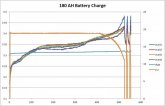
Here's a plot charging the 180AH battery with 19A. Vbat and Cur scale is on the right, cell voltage on the left. Time is in minutes. BMS turns off charging at 3.48V, and back on again at 3.35V. Charger set to 14V.
180AHFullCharge.jpg
 
Back
Top