diy solar

diy solar

Charging Solution for Lifepo4: AGM Charger? 13.5V PS? 15V PS?

PrivatePIlot

New Member
Joined
Nov 26, 2022
Messages
33
I'm in the final stages of building a 280ah LIfepo4 system.

BMS is a JK 200A with all the goodies, high and low temp cutoff, full programable, 2a balancing, etc.

I'm still a bit foggy on the technicalities of charging, and it's the last piece of the puzzle. Can someone answer the following questions for me please?

- Since I have a BMS I do not need a "special" LifePo4 charger since the BMS will keep things safe and managed, correct? I just need something that supplies the correct voltage (see next questions), at whatever amperage I want to charge at, right?

- The biggest bang for the buck (Cost vs amp output) seem to be automotive style chargers that support AGM which gets the voltage rates up higher to the levels that will achieve a 100% SOC on Lifepo4. Any reason I shouldn't opt for this if in the end since I already own one of these?

- Alternately I've found some switching power supplies in the 30-60A range that put out either 15v or 13.5V. 15V is too high, correct? Or will the BMS be OK with that and lower the voltage going to the battery? Or will it just kick off due to over voltage?

- 13.5V is safe but will not achieve a full 100% SOC, correct? What kind of SOC will I achieve using a 13.5V power supply for charging? I see different information online about 13.5v charging being enough to get a Lifepo4 to mid 90% SOC's, is this true? If so, this fits my needs just fine as I'm not looking to stress the pack anyways, a few lost AH's for added longevity is fine with me.

Thanks for all the advice!
 
Last edited:
- Since I have a BMS I do not need a "special" LifePo4 charger since the BMS will keep things safe and managed, correct? I just need something that supplies the correct voltage (see next questions), at whatever amperage I want to charge at, right?

Mostly. You want a charger that will operate inside the BMS limits and not rely on the BMS to protect the battery for routine operation.

- The biggest bang for the buck (Cost vs amp output) seem to be automotive style chargers that support AGM which gets the voltage rates up higher to the levels that will achieve a 100% SOC on Lifepo4. Any reason I shouldn't opt for this if in the end since I already own one of these?

You can get LFP fully charged at 13.8-14.6V. 13.8V is going to take longer and 14.6V may trigger BMS protection. 14.4V is a preferred max.

- Alternately I've found some switching power supplies in the 30-60A range that put out either 15v or 13.5V. 15V is too high, correct?

Yes.

Or will the BMS be OK with that and lower the voltage going to the battery?

No. BMS don't "regulate" anything except to allow or deny it. if the voltage goes over limits, the charger the circuit is opened and charging is not allowed.

Or will it just kick off due to over voltage?

Yes.

- 13.5V is safe but will not achieve a full 100% SOC, correct?

Correct.

What kind of SOC will I achieve using a 13.5V power supply for charging?

Hard to say. I'm very confident 13.6V gets you to 95%+, so 13.5V should get > 90%? I've never tried it.

I see different information online about 13.5v charging being enough to get a Lifepo4 to mid 90% SOC's, is this true? If so, this fits my needs just fine as I'm not looking to stress the pack anyways, a few lost AH's for added longevity is fine with me.

Optimal compromise between speed of charging, getting to high state of charge and minimizing charging stress (maximizing cycle life) is charging to 3.45V/cell or 13.8V to get about 98% charged.
 
Excellent, thanks for the info.

I've been reading a lot about the importance of the absorption phase with lfp's to achieve and maintain proper cell balancing, and if I'm understanding things correctly it seems that without 14.4v it may not reach absorption, but with a BMS with a full 2A balancing option will that still be a problem?

FWIW my charging situation while mobile (this is a micro-camper installation) can reach 14.4-14.5v so it will see higher voltages for charging in this situation.
 
Excellent, thanks for the info.

I've been reading a lot about the importance of the absorption phase with lfp's to achieve and maintain proper cell balancing, and if I'm understanding things correctly it seems that without 14.4v it may not reach absorption, but with a BMS with a full 2A balancing option will that still be a problem?

Most BMS start balancing at 3.4V/cell or 13.6V average.

Consider that "full 2A" balancing is misleading. That value is usually for a full 1V difference between cells. At the smaller 0.1-0.2V differences you'll likely see, you're looking at 0.2 to 0.4A - still better than passive.

Regularly charging > 13.6V and spending several hours per month there should be enough time to maintain balance with healthy cells.

FWIW my charging situation while mobile (this is a micro-camper installation) can reach 14.4-14.5v so it will see higher voltages for charging in this situation.

Perfect.
 
Last edited:
Consider that "full 2A" balancing is misleading. That value is usually for a full 1V difference between cells. At the smaller 0.1-0.2V differences you'll likely see, you're looking at 0.2 to 0.4A - still better than passive.

It's a JK b2a8s20p - I didn't cheap out, but did get a pretty good deal on Cyber Monday. Seems highly regarded, and I'm pretty sure the off grid garage fellow tested it and confirmed it's a real 2A discharge current.

Anyhow, sounds like I've found my combination, thanks again for all your insight and the time to reply.
 
1673145973921.png

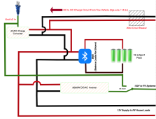
Hows this look for a tentative wiring diagram?

There is a pre existing fuse panel on the 12v house loads already so none is shown here, the new wiring will be just patched to that panel.

I thought about adding a ~200A breaker between the BMS and the inverter but since the inverter can be programmed with a cutoff amperage anyways (and maxes out at 200A before it cuts off regardless ) it seemed a bit unnecessary. Yes, I know we can't get the full 3000w out of the inverter (much less the surge rating of 6000w) with only a 200A BMS (It'll shut down at around 2400W) but that's fine, maximum draw with our typical usage pattern would be around 2000w on the inverter.

200A breaker on the charge circuit from the tow vehicle is basically to protect against a dead short if the charge circuit wire is damaged or whatever. It's doubtful that actual charge amperage would much exceed 100A, although 100-150 is certainly possible as the tow vehicle has a very high amperage DC to DC converter that is capable of pumping out over 150A.
 
Hows this look for a tentative wiring diagram?

Missing lots of overcurrent protection.

First, fuses and breakers are not installed to protect equipment. They are there to protect wires.

There is a pre existing fuse panel on the 12v house loads already so none is shown here, the new wiring will be just patched to that panel.

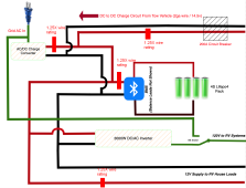
Wiring must include a single fuse off the battery 1.25X the max rating of the wire. All circuits must be protected by a fuse 1.25X the minimum wire rating.

1673152764765.png

Closest to the source is best.
 
Thx. Converter already has a built in output breaker and appropriate sized wire will be utilized.

House loads already have a separate fuse panel so putting a breaker/fuse on what will be basically a 12" run of wire headed directly to an existing fuse panel would be unnecessary, I would think? This is a very light duty circuit in the grand scheme of things as well - all interior lighting is LED (so very low draw), refrigerator is propane so the only draw is the control circuit, and other draws are small things like USB chargers etc. The heaviest draw is about 10A for the water pump. The entire house load circuit is on a 40A fuse and even that's overkill, with every light turned on and every possible load on all at once (highly unlikely but possible) total draw would probably max out at around 25A.

I'll add a breaker on the main output from the BMS.
 
Thx. Converter already has a built in output breaker and appropriate sized wire will be utilized.

The output breaker determines the min size of wire.

House loads already have a separate fuse panel so putting a breaker/fuse on what will be basically a 12" run of wire headed directly to an existing fuse panel would be unnecessary, I would think?

So, will the sum of the fuse amperages in the panel protect the wire? In most cases, no.

This is a very light duty circuit in the grand scheme of things as well - all interior lighting is LED (so very low draw), refrigerator is propane so the only draw is the control circuit, and other draws are small things like USB chargers etc. The heaviest draw is about 10A for the water pump. The entire house load circuit is on a 40A fuse and even that's overkill, with every light turned on and every possible load on all at once (highly unlikely but possible) total draw would probably max out at around 25A.

You don't protect a system based on your planned usage, you do it based on the system potential. A 3kW inverter @ 12V can pull 3000/12/.85 = 294A. I hope you're using marine grade 4/0 between your battery and inverter. If you truly never plan you use it, you use thinner wire that's appropriately fused.

I'll add a breaker on the main output from the BMS.

Make sure the breaker as an absurdly high AIC rating of 20,000 or more. Low AIC fuses and breakers can't protect wires from LFP. Class T fuses are preferred.
 
Pack is together and working well. Testing is going well.

Looking for more advice on charging. I'm getting mixed info on the necessity for a "special" Lifepo4 charger versus just using a power supply that can be dialed to ~14-14.4v. Some are saying to never use anything except a purpose-built Lifepo4 charger whereas a lot of info online suggests that so long as you're using a BMS (and don't over-volt past 14.4 and have it setup correctly to cutoff just in case) that a broad variety of sources can ultimately be used, even including lead-acid battery chargers in pinch.

The reason I'm leaning towards a PSU vs a special purpose-built lithium charger is cost per amp output. I want to be able to charge at around 60A when grid power (in the form of a regular 120v 15A household receptacle) is available, which in our typical usage pattern, may be short periods of time - so it's a "gobble as much energy as fast as possible when it's available" scenario.

Long story short, I can get a 60A bulletproof server PSU that can be adjusted to 14.4v for about $60CDN, but I'll pay many more times that for a comparable "special" Lifepo4 charger of comparable amp output.

My plan was to setup the BMS conservatively to disconnect charging at 3.35v (90% SOC) and not reconnect again until 3.25V, 80% SOC, or a bit higher if I wanted the PSU to maintain a tighter window. If I need or want to pump up to 100% SOC I can simply adjust the top end settings in the BMS.

I ultimately don't care if the PSU stays on constantly inside the 90% to 80% SOC window but isn't in active use actually charging.

Does this sound like a viable solution or is there something I'm missing?
 
Pack is together and working well. Testing is going well.

Looking for more advice on charging. I'm getting mixed info on the necessity for a "special" Lifepo4 charger versus just using a power supply that can be dialed to ~14-14.4v. Some are saying to never use anything except a purpose-built Lifepo4 charger.

These are usually the people selling said chargers.

whereas a lot of info online suggests that so long as you're using a BMS (and don't over-volt past 14.4 and have it setup correctly to cutoff just in case) that a broad variety of sources can ultimately be used, even including lead-acid battery chargers in pinch.

I'm in this group. If a charger charges to 13.8-4.4V and floats between 13.5 and 13.8V (flexibility here), it's pretty much fine. The biggest issue with converters is the typical wiring in an RV. The voltage drop can trigger the charger to change charging phase and shift to lower voltage/reduced current thus increasing charge time - which is opposite consumer expectation - LFP should charge faster.


The reason I'm leaning towards a PSU vs a special purpose-built lithium charger is cost per amp output. I want to be able to charge at around 60A when grid power (in the form of a regular 120v 15A household receptacle) is available, which in our typical usage pattern, may be short periods of time - so it's a "gobble as much energy as fast as possible when it's available" scenario. Long story short, I can get a 60A bulletproof server PSU that can be adjusted to 14.4v for about $60CDN, but I'll pay many more times that for a comparable "special" Lifepo4 charger of comparable amp output.

I would certainly consider this and use a server PSU for a specialized "float" application on a FLA bank.

My plan was to setup the BMS conservatively to disconnect charging at 3.35v (90% SOC) and not reconnect again until 3.25V, 80% SOC

Do not do this. You can't target SoC by voltage, and you don't want to use your BMS for routine cut-off. The BMS is a safety device, and it should only be used to prevent damage. Repeated triggering can wear out the FETs.
 
Do not do this. You can't target SoC by voltage, and you don't want to use your BMS for routine cut-off

OK, so just leave it set to stay connected to the PSU constantly (so long as the voltage is configured to the highest I want the SOC) is OK? It'll just float there? What cell voltage limits would I set the BMS for then?

I'd like to be conservative in my SOC window for longevity so staying within the ~10% to 90% window is my goal with occasional exceptions as needed.

So what voltage would I want to set the PSU for to top the pack to 90%? And 95% (occasionally)?

I went ahead and purchased the recommended PSU a short while ago and should have it early next week, FWIW.
 
OK, so just leave it set to stay connected to the PSU constantly (so long as the voltage is configured to the highest I want the SOC) is OK?

That's an option. This is the downside to using a power supply - external management required. Since you want fast charging, you need a high charge voltage. if you want low maintenance, you either externally manage it, or you set a lower float voltage... slower charging.

It'll just float there?

Depends.

What cell voltage limits would I set the BMS for then?

The same ones you should always set the BMS for - the published cell limits, so it can protect the cells. When your system is configured properly, you forget the BMS is there UNLESS something goes wrong because it never has to do anything. Your equipment needs to operate inside the limits of the BMS.

I'd like to be conservative in my SOC window for longevity so staying within the ~10% to 90% window is my goal with occasional exceptions as needed.

Good luck. The only way to do this with any reasonable success is to use a battery monitor that actually tracks true state of charge to signal the equipment. Even then, you need to periodically re-sync the battery monitor to 100% with a full charge. A Victron BMV has a relay that can be used to open or close a relay based on SoC, voltage and temperature.

So what voltage would I want to set the PSU for to top the pack to 90%? And 95% (occasionally)?

I'm guessing you missed this:

Do not do this. You can't target SoC by voltage, and you don't want to use your BMS for routine cut-off. The BMS is a safety device, and it should only be used to prevent damage. Repeated triggering can wear out the FETs.

3 main options:
  1. 14.4V - you manually turn off the charger within two hours when it hits this level. Fast charging.
  2. 13.8V - Slow charging. Will get to 70-80% at near max current, but the top-off will take 2-3 hours, and you'll hit 98% SoC.
  3. Externally managed with something - 14.4V when you want charging, stop charging based on some criteria.
 
Externally managed with something - 14.4V when you want charging, stop charging based on some criteria.

Is putting a solar charge controller between the charge source and the pack an option to *ensure* that charging is turned off before overcharging a viable solution?

That's my biggest concern especially since this unit is occasionally used by family and friends, so a long drawn out "Turn this switch off after such and such time, don't forget" type situation isn't ideal. I'd like an idiot-proof design, more or less. On commercial lifepo4 packs like Jackery's or whatever, how is this accomplished?
 
Is putting a solar charge controller between the charge source and the pack an option to *ensure* that charging is turned off before overcharging a viable solution?

Not an MPPT. With most, the source must be notably higher than the battery voltage to work.

You might find an inexpensive PWM controller that can go between them. PWM works by shorting the source to the battery and then interrupting the connection hundreds/thousands of times per second with a varying duty cycle to maintain voltage. I would use one rated for 25% more current than the PS can deliver.

That's my biggest concern especially since this unit is occasionally used by family and friends, so a long drawn out "Turn this switch off after such and such time, don't forget" type situation isn't ideal. I'd like an idiot-proof design, more or less.

Never underestimate the power of an idiot. Nothing is idiot-proof as the system may have underestimated the idiot.

On commercial lifepo4 packs like Jackery's or whatever, how is this accomplished?

Like a solar generator? They simply have built in chargers.
 
Alrighty, on further consideration I think I'm opting to shy away from the PSU charger option. Big amps for a low price is alluring, but not if it means a potentially fried battery - penny wise, pound foolish.

I found a local fellow selling a Wfco 50A purpose built Lifepo4 charger. More money than I'd liked to have spent, but I'll recoup a little reselling the old converter out of the trailer in the end, so it is what it is.

What converter? Did you mention it before? This "old converter" might be fine.

A WFCO "purpose built lfp charger" falls into:

These are usually the people selling said chargers.

Have you determined that your existing converter won't work?
 
Existing converter is absolutely 100% lead-acid only - the RV preexists the point manufacturers started putting switchable units in RV's. I know a lot of newer RV's are coming with SLA converters that can be switched into a lithium mode, and some others have the ability to add a module to manually kick them into bulk mode persistently for lithium usage, but the one in my camper wasn't in that category which is why I never mentioned it as an option.

From what I've gathered, being SLA only, it would have worked to an extent, but as soon as it fell out of 40A bulk mode into float mode the reality was that getting the SOC meaningfully higher on the lifepo4 pack was going to be a long, slow, probably incomplete process. Correct?
 
What converter make and model?

Will get the model details when I'm over at the camper next. Can't find a single image of the unit online at Amazon, eBay or even via Google image search despite a rather exhaustive hunt to find it without physically looking at it.
 
Back
Top