diy solar

diy solar

Check my motorhome Solar/battery system

Haskins

New Member
Joined
Nov 26, 2023
Messages
6
Location
Bakersfield
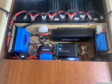
On the top of the picture I have two solar arrays coming in; one is 600w and the second 800w. The solar goes to two different Victron charge controllers. On the right I have my Cerbo-gx, Victron 30 amp charger when hooked into outside power. In the middle I have my dc-dc charger and renogy 3000w inverter. On the left I have 5 sok 206ah lithium batteries. From the inverter it goes to a transfer switch and then to the breaker panel of my motorhome. Any questions observations or concerns please let me know. Thank you for your time.

Just for reference you are looking down at the system. The dc-dc charger is flat on the ground.
 

Attachments

  • IMG_3219.jpeg
    IMG_3219.jpeg
    1.4 MB · Views: 23
Last edited:
Nice clean install.

You may already know this but i will throw the following out:

1. The chargers will get pretty hot when in use, especially mounted with the cooling fins oriented horizontally rather than vertically, The manual for the MPPT's says:

4.1. Mounting
Mount the solar charger vertically on a non-flammable substrate, with the electrical terminals facing downwards.
Observe a minimum clearance of 10cm [4"] under and above the solar charger for optimal cooling.


You might consider installing a fan(s) to help cool the devices. Otherwise their output will derate as heat rises.

The manual says:

The controller is operational up to 60°C, with a full rated output up to 40°C.
In case the solar charger heats up quicker than expected, pay attention to the way it has been mounted. Mount it in such a way
that the generated heat can dissipate.
Ideally mount the solar charger on a vertical surface with the terminals facing downwards.
If the solar charger is located in a closed enclosure, such as a cabinet, make sure that cold air can enter and hot air can leave the
enclosure
. Mount vents in the enclosure


2. I am not sure about the mini circuit breakers because I cannot see the specs. You might consider installing fuses between each device and the battery so that the breakers then merely serve as convenient on off switches for maintenance purposes.
 
Thank you for your observation. Here is the spec on the solar disconnects.
 

Attachments

  • IMG_3319.png
    IMG_3319.png
    322.5 KB · Views: 10
I tested breakers just like the ones you show in your photo, except they were rated at 60 amps. I bench tested them and noticed that they got up to about 135F at only 35 amps. I do not trust them as current limiting devices.

I do not know if they can be trusted as disconnect devices. I would think low voltage like 12v would be OK.

I am hoping others will comment on their use as merely a disconnect device.
 
For our RV I use Midnight Solar breakers with no problems since 2012. I don't use fuses because they tend to fail from vibration or in the case of glass AGC style fuses the end cap solder connection cold flows.
 
Any questions observations or concerns please
1, the Inerrupt rating of the main 300 amp fuse may not be adequate, holder mounting suspect.
2, there will be considerable heat build up, additional ventilation and vertical mounting of the solar controllers will help.
3, battery and fuse terminal protection covers, ' boots', for the more exposed terminals.
 
I like it. Tidy and good use of space.

Plans to expand the Solar? That 150/100 is huge!

Do you have the two MPPTs connected to the cerbo so they communicate?
 
1, the Inerrupt rating of the main 300 amp fuse may not be adequate, holder mounting suspect.
2, there will be considerable heat build up, additional ventilation and vertical mounting of the solar controllers will help.
3, battery and fuse terminal protection covers, ' boots', for the more exposed terminals.
Forgive me but what do you mean by interrupt rating of the fuse? Is it too large? Yeah I ran out of room, the 4/0 is stuff as can be so it just floats there and the zip tie mounts keep it from moving. All solar controllers are mounted vertical but I think I will add a spacer so they sit about 1/2 inch away from the wood. Thank you for your input.
 
One thing which stands out to me is the cerbo gx. I am not sure what this offers for you? Does it integrade with your renogy dc-dc charger/inverter? Otherwise it seems pointless in this use.( don't shoot me @sunshine_eggo :giggle:)
The cerbo connects all Victron equipment together and then sends it to Bluetooth or Wi-Fi so I can see what’s happening anywhere in the world.
 
I like it. Tidy and good use of space.

Plans to expand the Solar? That 150/100 is huge!

Do you have the two MPPTs connected to the cerbo so they communicate?
I only have room for one more 200w panel. Yeah when I got that 150/100 I was shocked. Yes all the Victron equipment is connected to the cerbo. I plan eventually to change out the dc-dc charger and the inverter to Victron so it all talks. Thanks for the observations!
 
I only have room for one more 200w panel. Yeah when I got that 150/100 I was shocked. Yes all the Victron equipment is connected to the cerbo. I plan eventually to change out the dc-dc charger and the inverter to Victron so it all talks. Thanks for the observations!
I just noticed a new victron orion 50 am model on the website. Pretty new, not sure when it came out.

The current orion chargers do not communicate with the rest of the system...
 
Yeah I have been waiting for a higher amp charger than just 30amp. It does have a “ve” port so maybe it does talk to the cerbo? Thanks I’ll look into it.
 
Nice clean setup!

We are looking to live full-time in a motorhome by September of 2025 and I definitely want to change the power over to 48v solar system.

I have installed a complete system at our off-grid cabin and it came out great. If I do say so myself lol. However, it would have never been possible without this forum.

Thanks for the thread and info!
 
In general looks good.

What I like to do that is slightly different is to have a breaker for each battery and run these all to a common ( + ) bus bar.

Sometimes it is really helpful to be able to isolate off each battery to diagnose and maintain a power system.
 
In general looks good.

What I like to do that is slightly different is to have a breaker for each battery and run these all to a common ( + ) bus bar.

Sometimes it is really helpful to be able to isolate off each battery to diagnose and maintain a power system.
That is what I did at my cabin because I used server rack batteries. Each has its own breaker. I would like to do that in our motorhome as well, if they fit.
 
Forgive me but what do you mean by interrupt rating of the fuse?
A fuse is designed to fail at a certain current. If the power source feeding the fuse is capable of very high fault current, the fuse has to 'withstand' that current, that is, not allow power to 'jump' the 'gap' in the failed fuse. Worst case if the BMS fails to limit the current is several thousand amps or more. The fuse type you have seems to be a link fuse, perhaps ANL or Mega. These have an interrupt rating of around 2000 amps.
The ideal fuse is class T, rated at 20,000 amps Interrupt, acceptable is MRBF, rated at 10,000 amps in a 12v system.

Your setup has a number of batteries in parallel. Should a single battery suffer an internal failure resulting in a 'short', the remaining batteries could deliver a combined high current into the failed battery. Whilst uncommon, its possible. A technique to prevent such a situation is to fit a fuse to each battery.
One solution is a MRBF fuse in a Blue sea holder,

 
Back
Top