The LF230 is rated at 4,000 cycles.As the cycle life to 80% initial capacity is 6000 cycles at 25C, not 4000 cycles.
Thanks to @1234enough for posting the link.
The LF230 is rated at 4,000 cycles.As the cycle life to 80% initial capacity is 6000 cycles at 25C, not 4000 cycles.
I suppose most of these Lifepo4 prismatic cells with aluminum cases have similar expansion thru SOC. So looking at how EV batteries are made imo could give good insight on how to DIY a battery..First, that battery is using Gafang cells, not EVE cells.
Second, that is a very professionally manufactured battery usingEV-battery-class manufacturing techniques and design.
Terminals welded to aluminum busbars, among other things.
Between the use of spacers and the use of bent/flexible busbars that can accommodate a limited amount of movement / expansion, that battery has clearly been designed to allow the Gafang cells to expand and contract during charge / discharge cycles (within limits), but I don’t see how you can conclude anything about best practice for a DIY battery using EVE 280Ah cells from this teardown.
That really wasn't the point of my post. The point of my post was that cell interconnect testing was done at max BMS capacity using 4ga wire which is highly flexible.Looks good! Yes with only a 4 cell pack it seems that expansion/compression isn’t a huge deal.
I think 4awg wire is only good for like 80amps conservatively. Yeah if that’s all you charge with at 12v 4awg busbars would workThat really wasn't the point of my post. The point of my post was that cell interconnect testing was done at max BMS capacity using 4ga wire which is highly flexible.
Has anyone that has issues with buss bars loosening ever try a NordLock washer?
I used them under extreme heat and vibration in my GTI stroker build when everything short of trying safety wire failed. 2 piece locking design, I'd bet they would never loosen.
Combine them with a distorted thread locknut and you'd never have to worry, in my opinion. Obviously you'd use some thread locker on the studs.
The wire is only 4 inches long so it handles much more than 80 amps. As was indicated in the linked post this entire battery configuration was tested at 150amps while obtaining temperature readings on the wires and terminals with MINIMAL rise of cell interconnect wire temperatures using 4ga.I think 4awg wire is only good for like 80amps conservatively. Yeah if that’s all you charge with at 12v 4awg busbars would work
Can you link the 280 data sheet pleaseI downloaded and read the LF280K datasheet. It says mostly the same thing as the LF230 datasheet (except, of course, some of the numbers are different). The interesting part is that the LF230 datasheet goes into a bit more detail about how the cells are cycled in the fixture and what the results are.
Can you link the 280 data sheet please

Now THAT is a proper datasheet. Someone needs to get that April 2022 datasheet into the Resource Section here - I can only find the outdated datasheet from March 2021.Believe this is the Eve data sheet you talk of
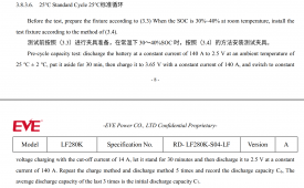
It says prepare the fixture:But I don’t see anything anywhere indicating Eve suggest the use of a rigid enclosure for a battery.


And I also see the new specification for 300kgf +/-20kgf which formalized the inputs we were provided n Eve through back channel in 2021.
But no question that a clamping fixture maintaining between 280kgf and 320kgf is the safest solution to maximize the cycle life of your Eve 280K cells…
So you are interpreting this to mean that there are no springs in the fixture they are using and the initial clamping force of 380kgf to 320kf @ 40% SoC will be allowed to drop as much as it wants towards full discharge and increase as much as it wants towards full charge?It says prepare the fixture:
View attachment 113354
And then says to put the cell in the fixture at 30%-40% SOC before cycling the cell:
View attachment 113355
The LF230 datasheet is much more clear about this. Neither of them say to do anything but put the cells in a rigid fixture.
Eve datasheet says nothing about busbars.I think if anything we all can for the most part agree that flexible busbars of some type should be used?
Agree. At 40% SOC, not 30%…This specification in the data sheet is simply the kgf that the cells were compressed with at 30-40% SOC IN A RIGID FIXTURE.. meaning that the kgf goes up as SOC rises. Far more than 320kgf..
I’m saying no matter what the fixture is, flexible busbars are imo best to prevent the possibility of any bms issues or bad cell connections.. I thought that would be easily agreed with. There is several 280ah prismatic cell sellers that now supply flexible busbars instead of solid busbars.. yes with a rigid fixture there is less expansion but it’s only less, so flexible busbars are still a good choiceEve datasheet says nothing about busbars.
If this new data means that rigid fixture can get used, rigid busbars may be OK.
If a sprinkler-calibrated 300kgf clamping fixture is being used that can allow for some expansion, flexible busbars are l likely preferable over rigid…
I don’t think you can conclude anything about the LF280K from the LF230K datasheet. Among other things, the LF230 may have one fewer fold in its pouch than the LF280 (how do the mechanical dimensions compare?),I do still agree with this,, however this new data sheet sure is kinda implying that it’s not necessary to do anything else other than rigid. In that rigid fixture the cells were beat to hell, still showing the cell made it 4000 cycles and had 80% of original capacity left.. easily imo double that 4000 if DOD is only like 70% and c-rates are much less.. so my very vague uneducated estimate is 8000 cycles minimum for most home batteries in a rigid fixture like the data sheet and still have 80% or original capacity left.
But if I was to use a rigid fixture. How do I know if the battery is actually at 40% SOC with such a flat voltage? Actual capacity can vary so much and voltage barely changes if at all


