diy solar

diy solar

Conflicting busbar calculators

lukemiller

New Member
Joined
Feb 27, 2021
Messages
6
I'm trying to decide if I should build my own busbars (for higher ampacity) or if the bars that came with my 230AH cells are worth using. I'm noticing conflicting calculators (top 2 google results) and wondering if anyone can help explain the differences:


This site lists a 1/8 by 3/4 copper bar at 215A:

This calculator has 1/8 by 3/4 copper bar at 72A:
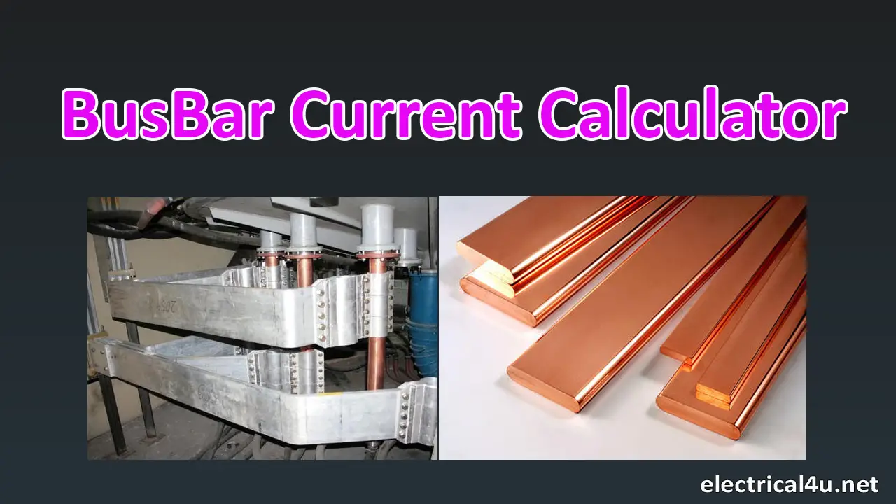
I know voltage drop and temp could effect ratings, but the two are pretty dramatically different. I'm leaning towards the lower number, chart #1 doesn't even seem to be calculating area correctly...

Included busbars are 2 stacked .75mm by 20mm wide, I think they are galvanized. By calculator #2 they can support somewhere around a wopping 18A. Well short of the 150A rating I'm looking for.
 
A) copper.org uses Table 5 from ATIS Standard T1.311 and assumes a given temperature rise over ambient.

B) electrical4u.net uses 1.2 * Busbar width in mm * Thickness in mm with no mention of temperature.

.125" x .75" = 60.5mm^2

60.5mm^2 falls between 1/0 and 2/0 gauge.

This company: https://www.westmarine.com/WestAdvisor/Marine-Wire-Size-And-Ampacity

says that for INSULATED marine wire, that cross section should be able to handle something between 285 and 330A.

Bus bars are typically not insulated, so they should be able to handle even more than insulated wire.

A) references a standard and is likely fine to use provided you pay attention to the temperature.

B) makes no mention of temperature. Given the dramatically lower ampacity, I expect there is a negligible temp rise.

It probably mostly comes down to how much temperature increase can you tolerate, and how much do you want to spend on bus bars?
 
Thanks, this clears things up a bit. I guess it really comes down to heat and voltage loss then. Copper.org's table is 30C over 40C ambient... that's pretty darn hot!

I just purchased 36" of 1/8 - 3/4 for less than $30 shipped, I don't anticipate much more than 100A but should help keep things nice and cool.

Guess I could stack the cheapos that came with the battery on top of the new ones as well.
 
The copper.com page specifically says it is for DC bus bars. The other site makes no mention of AC or DC. Is it possible that it is for AC?

Here is my thread where I posted about building my bus bars. I'll be adding to that thread soon.

 
150 amps out of 230 cells seems like a lot. I would use existing bars and have a second battery in parallel.
 
150 amps out of 230 cells seems like a lot. I would use existing bars and have a second battery in parallel.

I'm running 8x230 cells in series, max continuous is .5 capacity, so 115A continuous if the battery is full capacity. Normal loads will be more in the 70-90 range, but since I'm running a 3000W inverter I want to make sure my wiring is capable of at least 125A (24v) with some room for surge or accidental high loads.
 
I'm running 8x230 cells in series, max continuous is .5 capacity, so 115A continuous if the battery is full capacity. Normal loads will be more in the 70-90 range, but since I'm running a 3000W inverter I want to make sure my wiring is capable of at least 125A (24v) with some room for surge or accidental high loads.
A 3000 watt inverter can draw up to ~150 service amps at 24 volts.
150 service amps / .8 fuse headroom = 187.5 fault amps.
 
A 3000 watt inverter can draw up to ~150 service amps at 24 volts.
150 service amps / .8 fuse headroom = 187.5 fault amps.
I understand that I can't use the inverter to it's full potential. I don't need it either. My biggest appliance is a 1800W induction stove top, which I'd rather not run on a 2000W inverter.

Main thing is I'm nervous about the potential stress that size inverter can put on the system. My protection strategy is generously sized wiring, bus bars, and a breaker/battery protect to ultimately limit current.

Properly gauged wires and busbars should keep temp down, efficiency up (which will reduce amps drawn), and provide protection.

The bus bars that came with my batteries are .75mm x 20mm, so 15mm2 which puts them closer to 6awg. They are galvanized which looks like 1/2 the rating of copper. They are 2 stacked per bar which would put them at maybe 2x 60amps MAX (less than 120 total) current on the marine wire size chart? It's my understanding stacked busbars aren't exactly double.

If the above is correct, I would anticipate a considerable amount of voltage loss with a 70-90amp load, and probably heat. Stepping up to 1/8-3/4 copper bars seems to be more appropriate for the load and cheap efficiency increase.
 
This is anecdotal, so take it for what it's worth...

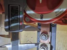
I initially was using 1/8" x 3/4" copper flat bar. I tested my system over a period of about 30 minutes, charging my 560 Ah battery bank (at ~55% state of charge) with the inverter/charger and a solar charge controller both active. Together, they were pushing about 100 amps into the battery bank. One of my bus bars between the Blue Sea switch and the Blue Sea Class T fuse (see picture below) was getting warm when all the other bus bars (positive and negative) were not warm. I say warm, meaning that I could tell it was not the same temperature as everything else when placing my finger on it. It wasn't hot.

Maybe it was a less than ideal connection, but when I took it all apart the connections were solid. So I'm not convinced that a connection issue was the cause. Instead, the 3/4" bus bar wasn't covering the entire pad of the fuse holder. Add in that the 3/8" stud further reduced the surface contact area and maybe there wasn't as much contact as the amps warranted.

I subsequently replaced the 1/8"x3/4" bar with one that is 1" wide (and thicker). That completely covers the fuse holder pad. After a test I found the bus bar to be the same temperature as everything else.

1647363596283.png
 
Back
Top