diy solar

diy solar

DIY busbars... 4/0 awg

If you connect in the order Battery Battery Inverter Inverter, all current goes through busbar cross section.
Connected Battery Inverter Inverter Battery, no part of the busbar carries more than half the current.

I was able to put lugs on top and bottom of busbar.
My setup is [Inverter/Inverter] Battery [Inverter/Inverter] for negative.

Inverter/Inverter Fuse Battery Fuse Inverter/Inverter for positive
(Two short cables spread out from battery to two fuses, and two inverters connect to each fuse.)
Mmmm, . . . I'm old, forgotten much of the old schooling, but my understanding of physics is that current flow is subject to the resistance of the surrounding material which is extremely low on a copper plate. This is how a shunt works. So if you have a 2 x 8 inch copper square significant current is flowing across the entire plate, even if the inputs and outputs are bolted closer together on one end. Partially to the point, there is resistance in the material which is why you want parallel battery cables to be as close in length as possible. The highest resistance is normally going to be around the connection points, so if you put the connections on either end you will still generate the most heat where it's bolted down. The center of a very long fat copper plate would likely to be close to ambient elevated only by the heat sink property of the metal around the resistance points. Technically moving the two connection points closer together will reduce the overall resistance, because you have a path thru less material, but the resistance in a chunk of copper is already so low I think it would be difficult to measure, and the electrons take all paths, proportional to the resistance of the surrounding material. At least that is how I remember it from school, happy to be enlightened otherwise.

Does look sexy and it's very clean to have real nice shiny copper plates, but from a practical standpoint just make sure you have a nice fat busbar with good tight connections. I'd go to 3/8 (10M), or at least 5/16" (8M) lugs on 4/0, copper or tin plated copper. Re-torque the connections after you've been running a week or two for paranoia, nut and split washer. I'd put a fuse/breaker on every wire transition. Example: Battery bus 4/0 300A fuse bus-bar 2x 2/0+150A breaker inverter. If you are DIY'ing the batteries directly to the bus make sure you have a breaker on the BMS or inline on the feed cable that matches the max expected current flow on that branch to/from the bus. Running the buses as described above makes it really clean to keep your connections straight, all the batteries on one edge, inverters on the other which will avoid confusion, and make the wiring easier when you are bending fat cable and bolting it down.
 
You know looking at all the home-brew battery busses (Including my own) it becomes quite apparent that this is a bit of an Achilles heel. Someone should engineer something simpler with stuff and go connections darnit!
 
Correct, current spreads out over may parallel paths according to resistance.
From a bolted connection, it has to spread out in all directions. Concentric rings of greater cross section.

The thing about my Battery Inverter Inverter Battery suggestion is you can cut busbar in half between the two inverters, and current flow is unchanged because zero current crossed that line (assuming identical loads and identical condition of batteries.) Busbar carries the load of one inverter.

Shorter busbar, more of the heating is from spreading, more average watts dissipated per linear inch of busbar. A long busbar connected at ends, approaches uniform current. More total power dissipated. Long busbar with two connections near middle, less power dissipation and more volume and surface area for heat to spread to, so runs cooling. A heat sink to air.
 
I’m not home with my book (and being lazy). Can you post that section? Thanks.
You just did, didn't you?

If it was a 2' section with ends terminated just outside in 75 degree lugs, I'd be concerned about the elevated temperature.
If a 2' section of high conduit fill and the same wire continued 10' in either direction in it's own conduit not shared with other wires, then I'd be confident heat would spread out and the entire wire would be cooler.
 
Correct, current spreads out over may parallel paths according to resistance.
From a bolted connection, it has to spread out in all directions. Concentric rings of greater cross section.

The thing about my Battery Inverter Inverter Battery suggestion is you can cut busbar in half between the two inverters, and current flow is unchanged because zero current crossed that line (assuming identical loads and identical condition of batteries.) Busbar carries the load of one inverter.

Shorter busbar, more of the heating is from spreading, more average watts dissipated per linear inch of busbar. A long busbar connected at ends, approaches uniform current. More total power dissipated. Long busbar with two connections near middle, less power dissipation and more volume and surface area for heat to spread to, so runs cooling. A heat sink to air.
Ahh.

To my point, once you get past a certain point on a block of copper it's kind of moot. I keep seeing people talking about 1000+ amp battery busses, but they don't have anything that can draw anywhere close to that number with the equipment they are using. You on the other hand . . . :p

You see i have this 2000W AIO inverter, and I want to hook 60KWH of battery to it... Sure thing, you need some #6 wire, and, . . . And then you can run the b*tch for about 30 hours wide open. on battery.
 
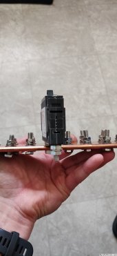
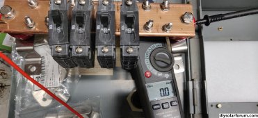
I too, am curious as to how you mounted the breakers.
They look like panel mount breakers (like Midnite or Outback), just without the panel.

The bus bars I have are brass :( I was not paying attention to that detail when I bought them. I think I need new ones :rolleyes:
 

Attachments

  • IMG_20231016_194133.jpg
    IMG_20231016_194133.jpg
    1.3 MB · Views: 36
If you connect in the order Battery Battery Inverter Inverter, all current goes through busbar cross section.
Connected Battery Inverter Inverter Battery, no part of the busbar carries more than half the current.

I was able to put lugs on top and bottom of busbar.
My setup is [Inverter/Inverter] Battery [Inverter/Inverter] for negative.

Inverter/Inverter Fuse Battery Fuse Inverter/Inverter for positive
(Two short cables spread out from battery to two fuses, and two inverters connect to each fuse.)

(might as well buy the 6 or 12 pk...)


It was actually easy. Working great so far.


View attachment 177684
Boy that's slick I like that
 
(might as well buy the 6 or 12 pk...)


It was actually easy. Working great so far.


View attachment 177684
I thought I was the only one who mounted breakers like that!!
It works quite well for my DIYs but I never posted any pictures of it.

Even used the same Carling Breakers.
 
An honest question: Why not just use DIN rail mounted breakers or is the breaker having 1 pole connected to the buss bar and the other not connected to the buss bar? I wasn't sure from the perspective of the photos?
 
Back
Top